• Product
  • Suppliers
  • Manufacturers
  • Solutions
  • Free tools
  • Knowledges
  • Experts
  • Communities
Search


Customization 6kV 10kV 20kV 22kV 33kV Oil-Immersed High-Voltage Side-Mounted Grounding Transformer source manufacturer

  • Customization 6kV 10kV 20kV 22kV 33kV Oil-Immersed High-Voltage Side-Mounted Grounding Transformer source manufacturer

Key attributes

Brand Rockwell
Model NO. Customization 6kV 10kV 20kV 22kV 33kV Oil-Immersed High-Voltage Side-Mounted Grounding Transformer source manufacturer
Rated voltage 24kV
Rated frequency 50/60Hz
Cooling mode ONAN
Series JDS

Product descriptions from the supplier

Description

Description

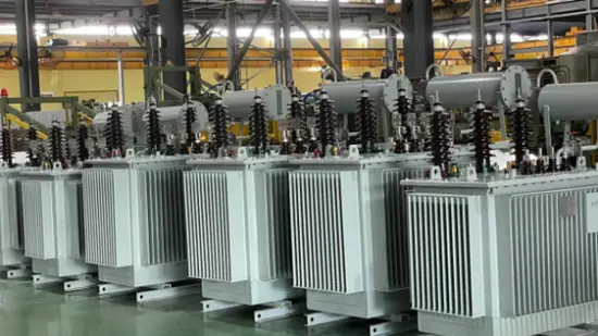
As the earliest specialized manufacturer of grounding transformers in China, we have built a complete independent industrial chain through decades of technological accumulation. Leveraging the long-term verified reliability of our products and our continuous innovation capabilities, we consistently lead the upgrading of industry standards, serving as a technological pioneer in the field of power safety equipment.

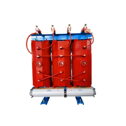
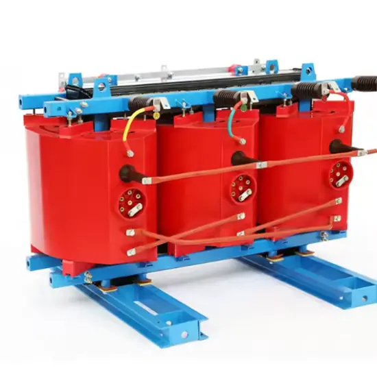
Earthing transformers are specially designed transformers. Their core function is to provide an artificial neutral point for power grids where the neutral point is either ungrounded or grounded through high impedance. This enables the neutral point to be grounded via an arc suppression coil or a small resistor.

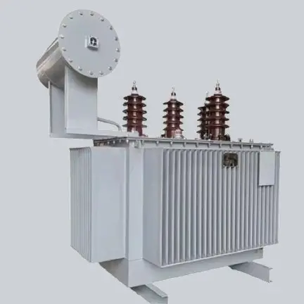
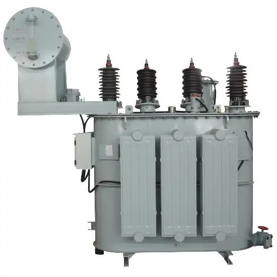
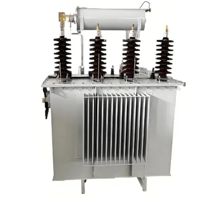
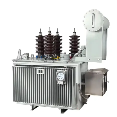
The oil-immersed, high-voltage bushing side-mounted type grounding transformer (commonly referred to in the industry as the "high-voltage side-mounted grounding transformer") is a specialized variant. As the name implies, the high-voltage bushings (i.e., the terminals of the high-voltage winding) of this type of transformer adopt a side-mounted design, positioned on the side of the transformer tank rather than on the top.

This structural design significantly reduces the overall installation height of the equipment, making it particularly suitable for space-constrained installations, such as indoor GIS (Gas-Insulated Switchgear) rooms, compact substations, and retrofit projects in existing substations.

Features

  • Space Optimization: The side-exit bushings significantly reduce the overall equipment height, enabling easy adaptation to low-clearance spaces or retrofit requirements in existing substations, saving civil engineering costs.

  • Flexible Grounding: Provides a stable neutral point, allowing flexible connection to a resistor cabinet / arc suppression coil. This effectively limits ground fault current, suppresses overvoltages, and enhances system safety and power supply continuity.

  • High Reliability:
    Impact Resistance: Designed to withstand the impact of unbalanced currents and zero-sequence currents generated by system single-phase-to-ground faults.
    Low Losses: Employs high-quality silicon steel cores and advanced manufacturing processes to ensure low no-load and load losses.
    Robust Insulation: Features a reliable high-voltage insulation structure with low partial discharge levels.
    Excellent Protection: High enclosure protection rating (IP), providing effective dust and moisture resistance.

  • Simplified Installation & Maintenance: Compact structure combined with the side-exit wiring design optimizes both on-site installation and subsequent maintenance operations.

Main Technical Parameters

Some of these earthing transformers cover voltage levels including:3.3kV / 6kV / 11kV / 15kV / 20kV / 22kV / 30kV / 33kV / 34.5kV / 36kV / 44kV / 66kV / 88kV / 110kV / 132kV / 145kV / 150kV / 220kV / 275kV / 330kV / 400kV, etc. The current withstand time ranges from 1s, 2s, 3s, 5s, 6s, 8s, 9s, 10s, 30s, 60s, 1hour to 2hours, and customization is available.

Parameter

Specification

Transformer type

Earthing transformer

Reference standard

IEC 60076

Rated power

334kVA

Rated voltage

6kV 10kV 20kV 22kV 33kV 

Number of phase

3

Vector of group

ZN

Cooling method

ONAN

Winding material

Copper

Cooling medium

Mineral oil

Zero phase sequence impedance at 75℃

58.62 Ohms/phase

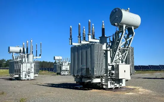
Main Application Areas

  • Power Generation Systems: Neutral grounding for auxiliary power systems in thermal/nuclear/hydroelectric plants

  • New Energy Stations: Grounding protection for collection systems in photovoltaic/wind/storage power plants

  • Industrial Power Distribution: Grounding for high-voltage motors and distribution systems in petrochemical, metallurgical, and mining industries

  • Transportation Power Systems: Grounding for railway traction substations, metro main substations, and port shore power systems

  • Special Scenarios: Grounding systems for precision power supply in data centers, hospitals, and laboratories


FAQ
Q: What is the relationship between the short-time capacity and short-circuit withstand time of an earthing/grounding transformer?
A:
The two are core parameters that restrict each other, following the inverse proportional relationship of "for the same equipment, the longer the withstand time, the smaller the short-time capacity" — because short-time capacity is calculated based on the thermal effect of fault current. Under the same fault current, the longer the withstand time, the more heat the equipment absorbs. To avoid insulation damage due to overheating, the rated short-time capacity must be reduced. For example, a 110kV earthing/grounding transformer has a short-time capacity of 5MVA under 30-second withstand time; if the withstand time is increased to 60 seconds, its short-time capacity may drop to about 3MVA (specifically, it must be implemented in accordance with the manufacturer's technical manual).
Q: How to coordinately determine the short-time capacity and short-circuit withstand time parameters of an earthing/grounding transformer during selection?
A:
Selection suggestions: The resistance value of the earthing resistor must be calculated in combination with the zero-sequence impedance of the earthing/grounding transformer, usually satisfying "earthing resistance R ≤ Uₚₕ/Iₚₑₐₖ" (Uₚₕ is the system phase voltage, Iₚₑₐₖ is the maximum short-time fault current allowed by the earthing/grounding transformer). At the same time, it must comply with the resistance value requirements for different grounding systems in the standard DL/T 621-1997 "Earthing of AC Electrical Installations".
Know your supplier
Online store
On-time delivery rate
Response time
100.0%
≤4h
Company overview
Workplace: 60000m² Total staff: Highest Annual Export(usD): 100000000
Workplace: 60000m²
Total staff:
Highest Annual Export(usD): 100000000
Services
Business Type: Design/Manufacture/Sales
Main Categories: High Voltage Electrical Apparatus/Electric transformer
Whole life care manager
Whole-life care management services for equipment procurement, use, maintenance, and after-sales, ensuring safe operation of electrical equipment, continuous control, and worry-free electricity consumption.
The equipment supplier has passed platform qualification certification and technical evaluation, ensuring compliance, professionalism, and reliability from the source.

Related Products

Related Knowledges

  • Impact of DC Bias in Transformers at Renewable Energy Stations Near UHVDC Grounding Electrodes
    Impact of DC Bias in Transformers at Renewable Energy Stations Near UHVDC Grounding ElectrodesWhen the grounding electrode of an Ultra-High-Voltage Direct Current (UHVDC) transmission system is located close to a renewable energy power station, the return current flowing through the earth can cause a rise in ground potential around the electrode area. This ground potential rise leads to a shift in the neutral-point potential of nearby power transformers, inducing DC bias (or DC offset) in their
    01/15/2026
  • HECI GCB for Generators – Fast SF6 Circuit Breaker
    1.Definition and Function1.1 Role of the Generator Circuit BreakerThe Generator Circuit Breaker (GCB) is a controllable disconnect point located between the generator and the step-up transformer, serving as an interface between the generator and the power grid. Its primary functions include isolating generator-side faults and enabling operational control during generator synchronization and grid connection. The operating principle of a GCB is not significantly different from that of a standard c
    01/06/2026
  • Distribution Equipment Transformer Testing, Inspection, and Maintenance
    1.Transformer Maintenance and Inspection Open the low-voltage (LV) circuit breaker of the transformer under maintenance, remove the control power fuse, and hang a “Do Not Close” warning sign on the switch handle. Open the high-voltage (HV) circuit breaker of the transformer under maintenance, close the grounding switch, fully discharge the transformer, lock the HV switchgear, and hang a “Do Not Close” warning sign on the switch handle. For dry-type transformer maintenance: first clean the porcel
    12/25/2025
  • How to Test Insulation Resistance of Distribution Transformers
    In practical work, insulation resistance of distribution transformers is generally measured twice: the insulation resistance between thehigh-voltage (HV) windingand thelow-voltage (LV) winding plus the transformer tank, and the insulation resistance between theLV windingand theHV winding plus the transformer tank.If both measurements yield acceptable values, it indicates that the insulation among the HV winding, LV winding, and transformer tank is qualified. If either measurement fails, pairwise
    12/25/2025
  • Design Principles for Pole-Mounted Distribution Transformers
    Design Principles for Pole-Mounted Distribution Transformers(1) Location and Layout PrinciplesPole-mounted transformer platforms should be located near the load center or close to critical loads, following the principle of “small capacity, multiple locations” to facilitate equipment replacement and maintenance. For residential power supply, three-phase transformers may be installed nearby based on current demand and future growth projections.(2) Capacity Selection for Three-Phase Pole-Mounted Tr
    12/25/2025
  • Transformer Noise Control Solutions for Different Installations
    1.Noise Mitigation for Ground-Level Independent Transformer RoomsMitigation Strategy:First, conduct a power-off inspection and maintenance of the transformer, including replacing aged insulating oil, checking and tightening all fasteners, and cleaning dust from the unit.Second, reinforce the transformer foundation or install vibration isolation devices—such as rubber pads or spring isolators—selected based on the severity of vibration.Finally, strengthen sound insulation at weak points of the ro
    12/25/2025

Related Solutions

Related Free tools
Haven't found the right supplier yet? Let matching verified suppliers find you. Get Quotation Now
Haven't found the right supplier yet? Let matching verified suppliers find you.
Get Quotation Now
Send inquiry
Download
Get the IEE Business Application
Use the IEE-Business app to find equipment, obtain solutions, connect with experts, and participate in industry collaboration anytime, anywhere—fully supporting the development of your power projects and business.