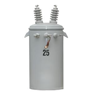
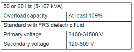
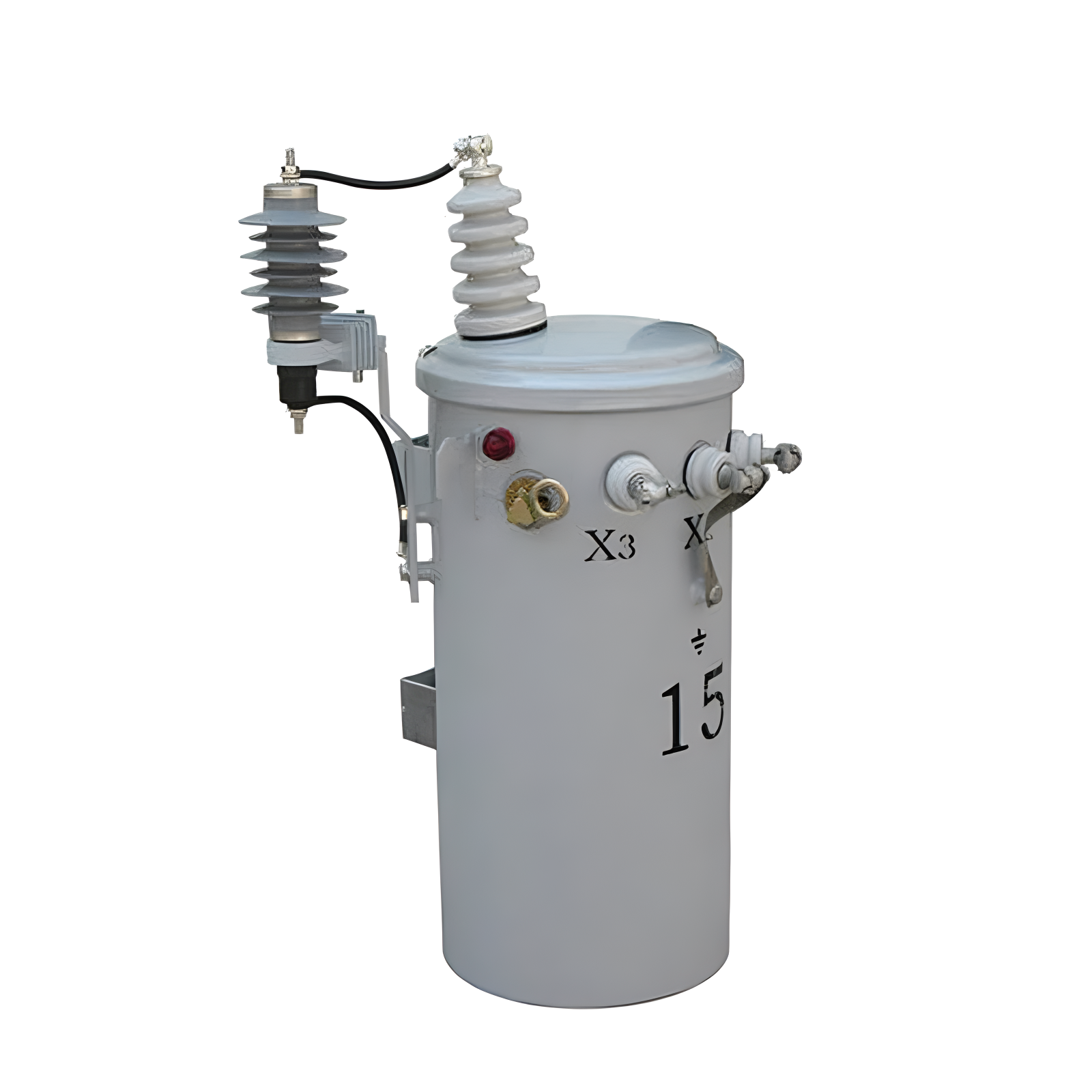
5-167 kVA single-phase overhead transformer
Key attributes
| Brand | Vziman |
| Model NO. | 5-167 kVA single-phase overhead transformer |
| Rated frequency | 50/60Hz |
| Primary voltage | 2400-34,500 V |
| Secondary voltage | 120-600 V |
| Capacity range | 5-167 kVA |
| Series | D-50 |
Product descriptions from the supplier
Descripton:
The single-phase overhead transformer ANSI boasts excellent load management performance, enabling it to handle load growth and temporary overloads with ease, without shortening the service life of the insulation system. The transformer's robust overload capacity allows power companies to operate stably under conditions of at least 109% of the rated load. Additionally, its compact and lightweight structural design further enhances the cost-effectiveness of the equipment and the efficiency of space utilization.
Features:
Performance and Design Advantages: This transformer is designed with the core objectives of enhancing performance and extending the insulation lifespan. It features a compact size and a lightweight design, and demonstrates outstanding performance in terms of safety and sustainability.
Optimization of the Insulation System: With excellent control over humidity and thermal stress, it effectively prolongs the service life of the insulation system and significantly enhances operational reliability.
Advanced Insulation Technology: Equipped with an advanced high-temperature insulation system, it integrates thermally upgraded kraft paper and FR3 dielectric fluid, and is paired with an optimized design of the core and coils, achieving technological upgrades.
Rich Specifications and Options: It provides a single-phase pole-mounted design with a power range of 5 - 167 kVA, and offers two temperature rise specifications of 75°C AWR and 65/75°C AWR to meet diverse requirements.
High-efficiency Advantages: The 75°C Average Winding Rise (AWR) configuration of the PEAK transformer can achieve the same power ratings as devices rated at 65°C AWR that are larger in size and heavier in weight, realizing high efficiency and compactness.
Outstanding Overload Capacity: The PEAK transformer with a 65/75°C slash rating has a nameplate overload capacity while having a size similar to that of traditional transformers, ensuring operation under special working conditions.
Compliance with High Standards: Its performance fully meets or exceeds industry standards such as ANSI and NEMA, and also satisfies the energy efficiency requirements of DOE, ensuring reliable quality.
Flexible Protection Design: It supports two design schemes, namely traditional and CSP, and provides diverse overcurrent protection options to meet the protection needs of different application scenarios.
Reliable Material Selection: The core and coils are carefully designed with the aim of achieving high reliability and a low on-site failure rate, and two materials, grain-oriented steel and amorphous steel, are provided for users to choose according to their needs.
Technical Parameters:
Specifications:
Meets or exceeds ANSI, NEMA and DOE2016 standards
IEEE, C57.12.00, C57.12.20, C57.12.31, C57.12.35, C57.12.90, C57. 91 and C57.154
NEMA standards, NEMA TR 1 (R2000)
Department of Energy Efficiency Standard, 10 CFR Part 431
Tank coating exceeds IEEE Std C57.12.31-2010 standard
Cover with a minimum dielectric strength of 8 kV
FR3 fluid
Cores and coils designed for high reliability and low field failure rates: Available in grain-oriented electrical or amorphous steel
Heavy-duty lifting lugs and hanger brackets per ANSI requirements up to 4500 lbs
The transformer shall be designed in accordance with this specification and shall have an Average Winding Rise (AWR) of one of the following:
55/75 °C, 65/75 °C, 75 °C
The applicable AWR rating shall be specified on the inquiry
The transformer shall be designed in accordance with this specification and shall have one of the following kVA ratings:
5, 10, 15, 25, 37.5, 50, 75, 100, 167
The applicable kVA rating shall be specified on the inquiry
Quality System ISO 9001 certified

Related Products


Related Knowledges
-
 Impact of DC Bias in Transformers at Renewable Energy Stations Near UHVDC Grounding ElectrodesImpact of DC Bias in Transformers at Renewable Energy Stations Near UHVDC Grounding ElectrodesWhen the grounding electrode of an Ultra-High-Voltage Direct Current (UHVDC) transmission system is located close to a renewable energy power station, the return current flowing through the earth can cause a rise in ground potential around the electrode area. This ground potential rise leads to a shift in the neutral-point potential of nearby power transformers, inducing DC bias (or DC offset) in their01/15/2026
 -
 HECI GCB for Generators – Fast SF6 Circuit Breaker1.Definition and Function1.1 Role of the Generator Circuit BreakerThe Generator Circuit Breaker (GCB) is a controllable disconnect point located between the generator and the step-up transformer, serving as an interface between the generator and the power grid. Its primary functions include isolating generator-side faults and enabling operational control during generator synchronization and grid connection. The operating principle of a GCB is not significantly different from that of a standard c01/06/2026
 -
 Distribution Equipment Transformer Testing, Inspection, and Maintenance1.Transformer Maintenance and Inspection Open the low-voltage (LV) circuit breaker of the transformer under maintenance, remove the control power fuse, and hang a “Do Not Close” warning sign on the switch handle. Open the high-voltage (HV) circuit breaker of the transformer under maintenance, close the grounding switch, fully discharge the transformer, lock the HV switchgear, and hang a “Do Not Close” warning sign on the switch handle. For dry-type transformer maintenance: first clean the porcel12/25/2025
 -
 How to Test Insulation Resistance of Distribution TransformersIn practical work, insulation resistance of distribution transformers is generally measured twice: the insulation resistance between thehigh-voltage (HV) windingand thelow-voltage (LV) winding plus the transformer tank, and the insulation resistance between theLV windingand theHV winding plus the transformer tank.If both measurements yield acceptable values, it indicates that the insulation among the HV winding, LV winding, and transformer tank is qualified. If either measurement fails, pairwise12/25/2025
 -
 Design Principles for Pole-Mounted Distribution TransformersDesign Principles for Pole-Mounted Distribution Transformers(1) Location and Layout PrinciplesPole-mounted transformer platforms should be located near the load center or close to critical loads, following the principle of “small capacity, multiple locations” to facilitate equipment replacement and maintenance. For residential power supply, three-phase transformers may be installed nearby based on current demand and future growth projections.(2) Capacity Selection for Three-Phase Pole-Mounted Tr12/25/2025
 -
 Transformer Noise Control Solutions for Different Installations1.Noise Mitigation for Ground-Level Independent Transformer RoomsMitigation Strategy:First, conduct a power-off inspection and maintenance of the transformer, including replacing aged insulating oil, checking and tightening all fasteners, and cleaning dust from the unit.Second, reinforce the transformer foundation or install vibration isolation devices—such as rubber pads or spring isolators—selected based on the severity of vibration.Finally, strengthen sound insulation at weak points of the ro12/25/2025
Related Solutions
-
 Choosing Vizman Distribution Transformers: Innovative Customization to Meet Diverse Power NeedsDistribution transformers are the heart of local electricity distribution systems. They step down voltage, enabling safe and efficient power supply to homes and businesses.At Vizman Electric Power Technology Co., Ltd., we understand the critical role of distribution transformers in the energy ecosystem. That's why we specialize in manufacturing high-quality distribution transformers, providing tailored solutions to meet diverse energy needs.1.Solutions Offered by Vizman Electric Power Technology04/16/2025
 -
 SF6 Circuit Breaker Solutions in High-Voltage Power Systems: A Case Study of VZIMAN Company1. Challenges in High-Voltage Power Systems1.1 High-voltage power systems, as the core of power transmission, face critical challenges:Equipment Performance Limits: With increasing voltage levels (e.g., 500kV and above), traditional circuit breakers struggle to meet high breaking capacities (over 40kA) and rapid insulation recovery requirements.Overvoltage Risks: Switching capacitive loads (e.g., capacitor banks) may cause reignition, leading to dangerous overvoltages.Poor Environmental Ada05/13/2025
 -
 VZIMAN Company SF6 Circuit Breaker Solutions for Renewable Energy Grid Integration1. Current Challenges in Renewable Energy Grid Integration1.1 Grid Frequency Fluctuations and Stability IssuesThe intermittency and variability of renewable energy sources (e.g., wind and solar) lead to frequent grid frequency changes. Traditional circuit breakers struggle to respond rapidly to such dynamic loads, potentially causing equipment damage or regional blackouts. For instance, during sudden drops in wind power or abrupt solar output fluctuations, the grid must isolate faults within m05/13/2025


