| Brand | Switchgear parts |
| Model NO. | 40.5kV-1000kV Silicone rubber high-voltage hollow composite insulator |
| Rated voltage | 40.5kV |
| 额定弯曲负荷 | 5kN |
| Series | HCI |
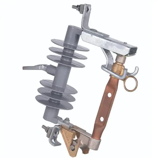
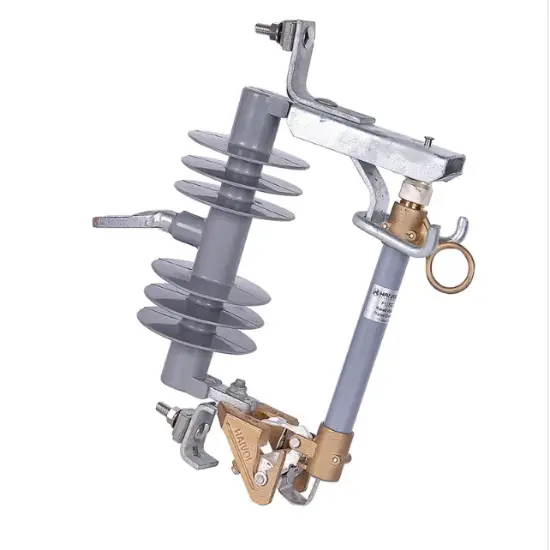
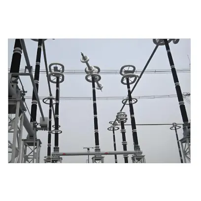
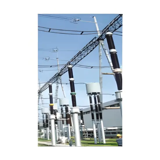
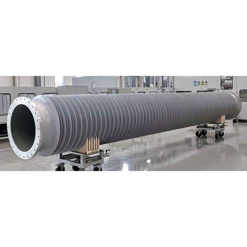
Hollow composite insulator is an important component of high-voltage electrical products composed of epoxy glass fiber wrapped tube, silicone rubber umbrella cover (HTV), and aluminum alloy flange accessories. Hollow composite insulators are mainly used in electrical equipment such as circuit breakers, load switches, isolating switches, grounding switches, transformers, bushings, cable terminations, and lightning arresters.
Product advantages
Excellent explosion-proof performance, even in the event of internal overpressure or other external damage, there is no risk of fatal explosion. In earthquake prone areas, the safety performance is extremely high, the weight is light, reducing the risk of damage during transportation and installation, and also reducing the cost and difficulty of transportation and installation. Extremely high insulation level, no need for additional surface coating in humid environments, still has extremely high electrical performance in AC and DC applications. Due to the hydrophobicity and transferability of silicone rubber, the surface does not require cleaning. Excellent UV resistance and aging resistance. The delivery time is significantly shorter than that of porcelain insulators. The materials are recognized as excellent environmental protection and harmless to health and safety.
Performance of epoxy resin glass fiber wrapped pipe
| Property | Unit | Value |
|---|---|---|
| Density | g/cm³ | ≥ 1.9 |
| Bending Strength | MPa | ≥ 120 |
| Elastic Modulus | GPa | ≥ 20 |
| Glass Transition Temperature (TG) | °C | 130℃ - 140℃ |
| Dielectric Loss | - | 3.1 × 10⁻² |
| Dielectric Constant | - | 4.0 |
| Volume Resistivity | Ω·m | 2.6 × 10¹² |
| 100h Water Diffusion Test | - | Pass |
| Dielectric Strength | kV/mm | 12 |
Performance of Organic Composite Umbrella Skirt Cover Material
| Property | Unit | Value |
|---|---|---|
| Solidity (Shore A) | - | 65-70 |
| Tear Strength | kN/m | ≥ 12 |
| Tensile Strength | MPa | ≥ 4.5 |
| Elongation at Break | % | ≥ 200 |
| Volume Resistivity | Ω·m | 7×10¹⁴ |
| Dielectric Constant | - | 3 ~ 4 |
| Dielectric Strength | kV/mm | ≥ 20 |
| Tracking and Erosion Resistance | - | TMA4.5 |
| Flame Retardance | - | FV-0 |
The performance requirements and quality control of the end metal flange accessories are made of high-quality aluminum alloy through metal mold pressure casting, T6 state treatment, no pinholes, good air tightness, and higher mechanical strength; The surface has undergone shot blasting treatment, providing better corrosion resistance.
Product Specifications
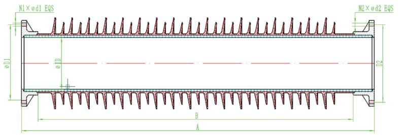
| Type | Rated Voltage Ur (kV) | Creepage Distance (mm) | Dry Arc Distance (mm) | 1min Power Frequency Withstand Voltage (kV) | Lightning Impulse Withstand Voltage (kV) | Inner Diameter ID (mm) | Mounting Hole Distance D (mm) | Structural Height H±2 (mm) | Bending Load (kN) | Internal Pressure Test (MPa) | n | d | ||
|---|---|---|---|---|---|---|---|---|---|---|---|---|---|---|
| MM L | SM L | MS P | SI P | |||||||||||
| HCI-40.5/5 | 40.5 | 1040 | 355 | 95 | 200 | 130 | 218 | 525 | 5 | 12.5 | 0.8 | 3.2 | 8 | 11 |
| HCI-40.5/4.8 | 40.5 | 1260 | 415 | 95 | 200 | 585 | 4.8 | 12 | ||||||
| HCI-52/4.8 | 52 | 1400 | 475 | 95 | 250 | 645 | 4.8 | 12 | ||||||
| HCI-52/4 | 52 | 1650 | 535 | 95 | 250 | 705 | 4 | 10 | ||||||
| HCI-72.5/4 | 72.5 | 1820 | 595 | 155 | 325 | 765 | 4 | 10 | ||||||
| HCI-72.5/3.2 | 72.5 | 2800 | 835 | 155 | 325 | 1005 | 3.2 | 8 | ||||||
| HCI-40.5/7.5 | 40.5 | 1050 | 370 | 95 | 200 | 154 | 220 | 540 | 7.5 | 18.8 | 16 | 11 | ||
| HCI-40.5/7 | 40.5 | 1270 | 430 | 95 | 200 | 600 | 7 | 17.5 | ||||||
| HCI-52/7 | 52 | 1500 | 490 | 95 | 250 | 660 | 7 | 17.5 | ||||||
| HCI-52/5.6 | 52 | 1700 | 550 | 95 | 250 | 720 | 5.6 | 14 | ||||||
| HCI-72.5/5.6 | 72.5 | 1900 | 610 | 155 | 325 | 780 | 5.6 | 14 | ||||||
| HCI-72.5/4.4 | 72.5 | 2300 | 730 | 155 | 325 | 900 | 4.4 | 11 | ||||||
| HCI-100/5.6 | 100 | 2540 | 790 | 165 | 380 | 960 | 5.6 | 14 | ||||||
| HCI-100/4.5 | 100 | 3200 | 970 | 205 | 450 | 1140 | 4.5 | 11.3 | ||||||
| HCI-126/4.5 | 126 | 3200 | 970 | 205 | 450 | 1140 | 4.5 | 11.3 | ||||||
| HCI-126/4 | 126 | 4000 | 1210 | 255 | 550 | 1380 | 4 | 10 | ||||||
| HCI-145/4.5 | 145 | 3640 | 1090 | 230 | 450 | 1260 | 4 | 10 | ||||||
| HCI-145/3.5 | 145 | 4500 | 1330 | 305 | 650 | 1500 | 3.5 | 8.8 | ||||||
| HCI-170/3.5 | 170 | 4280 | 1270 | 305 | 650 | 1440 | 3.5 | 8.8 | ||||||
| HCI-170/3 | 170 | 5300 | 1570 | 355 | 750 | 1740 | 3 | 7.5 | ||||||
| HCI-126/6 | 126 | 4000 | 970 | 205 | 450 | 190 | 312 | 1360 | 6 | 15 | ||||
| HCI-100/6.4 | 100 | 2600 | 730 | 165 | 380 | 198 | 260 | 900 | 6.4 | 16 | ||||
| HCI-100/5 | 100 | 3100 | 850 | 205 | 450 | 1020 | 5 | 12.5 | ||||||
| HCI-126/5 | 126 | 3310 | 910 | 205 | 450 | 1080 | 5 | 12.5 | ||||||
| HCI-126/4.5 | 126 | 4100 | 1090 | 255 | 550 | 1260 | 4.5 | 6.8 | ||||||
| HCI-145/4.8 | 145 | 3750 | 1088 | 205 | 450 | 1258 | 4.8 | 12 | ||||||
| HCI-145/4.0 | 145 | 4640 | 1328 | 305 | 650 | 1498 | 4 | 10 | ||||||
| Type | Rated Voltage Ur (kV) | Creepage Distance (mm) | Dry Arc Distance (mm) | 1min Power Frequency Withstand Voltage (kV) | Lightning Impulse Withstand Voltage (kV) | Inner Diameter ID (mm) | Mounting Hole Distance D (mm) | Structural Height H±2 (mm) | Bending Load (kN) | Internal Pressure Test (MPa) | n | d | ||
|---|---|---|---|---|---|---|---|---|---|---|---|---|---|---|
| MM L | SM L | MS P | SI P | |||||||||||
| HCI-170/4.0 | 170 | 4420 | 1268 | 305 | 650 | 198 | 260 | 1438 | 4 | 10 | 0.8 | 3.2 | 16 | 11 |
| HCI-170/3.5 | 170 | 5306 | 1508 | 355 | 750 | 1678 | 3.5 | 8.8 | 10 | 14 | ||||
| HCI-100/9 | 100 | 2600 | 730 | 165 | 380 | 248 | 342 | 930 | 9 | 22.5 | ||||
| HCI-100/8 | 100 | 3110 | 850 | 205 | 450 | 1050 | 8 | 20 | ||||||
| HCI-126/8 | 126 | 3300 | 910 | 205 | 450 | 1010 | 8 | 20 | ||||||
| HCI-126/7 | 126 | 4100 | 1090 | 255 | 550 | 1290 | 7 | 17.5 | ||||||
| HCI-145/7.4 | 145 | 4500 | 1210 | 255 | 550 | 1410 | 7.4 | 18.5 | ||||||
| HCI-145/6.5 | 145 | 5000 | 1330 | 305 | 650 | 1500 | 6.5 | 16.3 | ||||||
| HCI-170/6.5 | 170 | 5300 | 1390 | 305 | 650 | 1590 | 6.5 | 16.3 | ||||||
| HCI-170/5.6 | 170 | 5700 | 1510 | 355 | 750 | 1710 | 5.6 | 14 | ||||||
| HCI-252/4.6 | 252 | 7700 | 1990 | 435 | 950 | 2190 | 4.6 | 11.5 | ||||||
| HCI-252/3.6 | 252 | 8600 | 2220 | 460 | 1050 | 2400 | 3.6 | 9 | ||||||
| HCI-252/15 | 252 | 7650 | 1930 | 435 | 950 | 260 | 445 | 2190 | 15 | 37.5 | 16 | 17.5 | ||
| HCI-252/12.5 | 252 | 8700 | 2190 | 460 | 1050 | 2450 | 12 | 30 | ||||||
| HCI-300/12 | 300 | 9400 | 2380 | 505 | 1050 | 2640 | 12 | 30 | ||||||
| HCI-300/10 | 300 | 10200 | 2580 | 505 | 1050 | 2840 | 10 | 25 | ||||||
| HCI-252/15 | 252 | 7650 | 1930 | 435 | 950 | 280 | 445 | 2190 | 15 | 37.5 | ||||
| HCI-252/12.5 | 252 | 8700 | 2190 | 460 | 1050 | 2450 | 12 | 30 | ||||||
| HCI-300/12 | 300 | 9400 | 2380 | 505 | 1050 | 2640 | 12 | 30 | ||||||
| HCI-300/10 | 300 | 10200 | 2580 | 505 | 1050 | 2840 | 10 | 25 | ||||||
| HCI-800/20 | 800 | 27900 | 6840 | 1050 | 2400 | 300 | 348-348 | 2680x3 | 20 | 50 | 4 | 28 | ||
| HCI-252/12 | 252 | 8900 | 2260 | 460 | 1050 | 510 | 2500 | 12 | 30 | 16 | 18 | |||
| HCI-252/6 | 252 | 9650 | 2400 | 460 | 1050 | 348-348 | 2800 | 6 | 15 | 4 | 28 | |||
| HCI-252/5 | 252 | 8600 | 2290 | 460 | 1050 | 345 | 456-466 | 2542 | 5 | 10 | 20 | 13.5 | ||
| HCI-170/5 | 170 | 5100 | 1497 | 305 | 650 | 358 | 432 | 1757 | 5 | 12.5 | 24 | 13.5 | ||
| HCI-170/5 | 170 | 6400 | 1822 | 355 | 750 | 2080 | 5 | 12.5 | ||||||
| HCI-252/12.5 | 252 | 7600 | 2147 | 435 | 950 | 2407 | 5 | 12.5 | ||||||
| HCI-252/5 | 252 | 7900 | 2210 | 460 | 1050 | 2470 | 5 | 12.5 | ||||||
| HCI-300/5 | 300 | 9400 | 2602 | 505 | 1050 | 2862 | 5 | 12.5 | ||||||
| HCI-420/4 | 420 | 10800 | 2992 | 750 | 1550 | 3252 | 4 | 10 | ||||||
| HCI-420/3 | 420 | 14280 | 3900 | 750 | 1550 | 4160 | 3 | 7.5 | ||||||
| HCI-550/6 | 550 | 18800 | 4767 | 810 | 1800 | 375 | 460-586 | 5020 | 6 | 15 | 16 | 11.5-16 | ||
| HCI-550/10 | 550 | 15800 | 4050 | 810 | 1800 | 486 | 590-730 | 4330 | 10 | 25 | ||||
| HCI-550/10 | 550 | 17000 | 4720 | 810 | 1800 | 486 | 5000 | 10 | 25 | |||||
| HCI-750/8 | 750 | 30600 | 7690 | 960 | 2400 | 486 | 885-1010 | 8000 | 8 | 20 | 24 | 24 | ||
| HCI-550/12 | 550 | 18500 | 4477 | 810 | 1800 | 720 | 5037 | 12 | 30 | |||||
| HCI-750/20 | 750 | 31500 | 7540 | 960 | 2400 | 720 | 8100 | 20 | 50 | |||||
| HCI-1000/20 | 1000 | 45000 | 11000 | 1200 | 2760 | 720 | 11560 | 20 | 50 | |||||
| HCI-1000/20 | 1000 | 45500 | 10720 | 1200 | 2760 | 1000 | 1180-1200 | 11500 | 20 | 50 | 26-32 | 28 | ||
It is widely used in 40.5-145kV GIS/HGIS substations, high-voltage switchgear, power transmission lines, and railway electrification systems. Core parameters: Rated voltage 40.5/66/110/145kV, rated mechanical load ≥30kN, creepage distance 25-31mm/kV (customizable for heavy pollution), operating temperature -40℃~+80℃. For example, the 145kV model has a typical insulation distance of 1300mm and 1-minute power frequency withstand voltage of 4900V. It is ideal for high-altitude, coastal salt fog, and industrial heavy pollution areas.
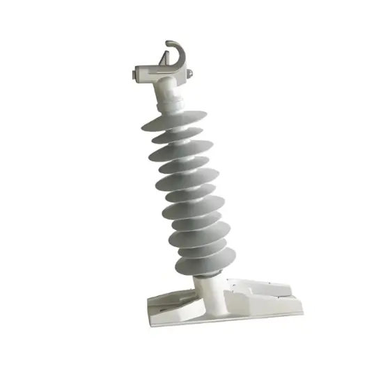
Its core function is to provide electrical insulation and mechanical support for high-voltage equipment (such as GIS, circuit breakers, and bushings) in 40.5-145kV power systems. The structure consists of three key parts: a glass fiber reinforced epoxy resin core tube (bearing mechanical load), a silicone rubber shed (providing creepage distance and environmental protection), and metal end fittings (ensuring firm connection). It features a hollow through design, which is compatible with internal gas insulation or conductor penetration scenarios.