• Product
  • Suppliers
  • Manufacturers
  • Solutions
  • Free tools
  • Knowledges
  • Experts
  • Communities
Search


30-800kVA 3-Phase AC Power Voltage Stabilizer

  • 30-800kVA 3-Phase AC Power Voltage Stabilizer
  • 30-800kVA 3-Phase AC Power Voltage Stabilizer
  • 30-800kVA 3-Phase AC Power Voltage Stabilizer

Key attributes

Brand RW Energy
Model NO. 30-800kVA 3-Phase AC Power Voltage Stabilizer
Rated capacity 80kVA
Series SWB-S

Product descriptions from the supplier

Description

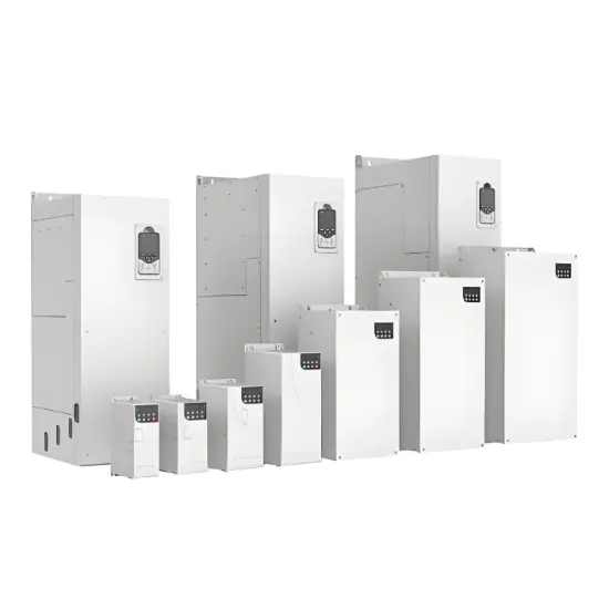
SBW-S、DBW-S series intelligent numerical control (microcomputer type) compensated AC power regulators are based on the perfect combination of traditional high-power compensated voltage regulators and modern intelligent control technology, allowing users to enjoy the reliability and convenience of parameter setting and maintenance brought by modern advanced control circuits, highlighting the safety, stability Energy saving and humanization of man-machine interface. The regulated power supply can be equipped with a variety of intelligent interfaces to realize the functions of "remote signaling, telemetry and remote control".

Features

  • Delay output function (add output contactor).

  • Lightning protection device: it can provide good surge protection in case of instantaneous change of power grid and induced lightning stroke.

  • EMI filtering device: it can effectively filter the harmonic interference of power grid.

  • Phase sequence and phase loss protection function.

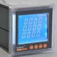
  • RS485 interface: realize remote control, remote signaling and telemetry function.

It can be widely used in industrial and mining enterprises, scientific research, posts and telecommunications, military, railway, transportation, hospitals, elevators, bowling equipment, air conditioners, hotels and other places with high requirements for power grid power supply.The normal operating conditions of sbw-s and dbw-s series intelligent control (single chip microcomputer control) complementary AC power regulators are:

  • temperature:-15°C - 40°C.

  • Altitude:less than 1000m.

  • Relative humidity:<90%.

  • The relative humidity installation site shall be free of gas, steam, chemical deposition, dust, dirt and other explosive and corrosive media that seriously affect the insulation strength of regulated power supply.

  • The installation site shall be free from serious vibration and turbulence.

  • Any special use conditions that do not meet the above provisions shall be determined through consultation with the user and our factory.

Parameters

image.png

image.png

Wiring diagram

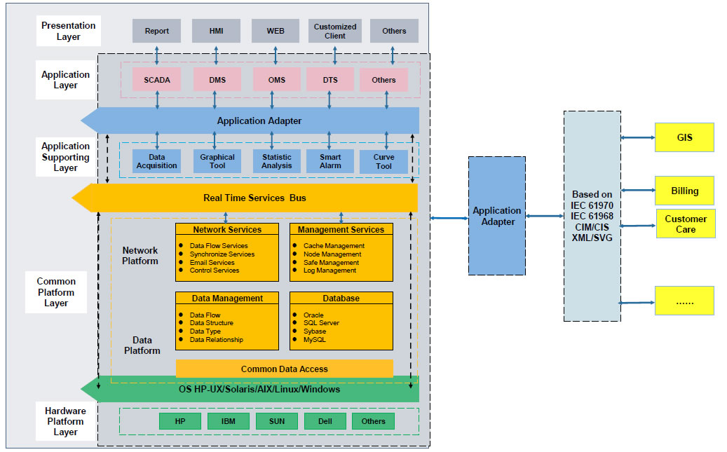
SBW-S、DBW-S series intelligent numerical control (single chip microcomputer control) compensation AC power regulator is mainly composed of input circuit breaker QF, three-phase voltage regulating transformer TB, three-phase voltage regulating transformer TVV, servo motor control and transmission mechanism, voltage stabilizing / bypass transfer switch and protection circuit. The electrical principle of the main circuit is shown in the figure below.

企业微信截图_17213497118363.png

企业微信截图_17213498418096.png

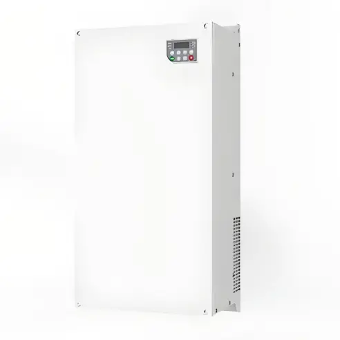
1.stable Voltage indicator lighting

2.Intelligent control display

3.Stop button

4.Mian power switch

5.Control loop fuse

6.Control power transform

7.gird/stabilization switch

8.Voltage regulating transform

9.Input terminal block

10.output terminal block

11. Compensation transform

12.cable entry and exit hole

  • Voltage stabilizing indicator.

  • Intelligent control display.

  • Stop button.

  • Main power switch.

  • Control circuit fuse.

  • Control power transformer.

  • Mains / voltage stabilizing transfer switch.

  • Voltage regulating transformer (auxiliary transformer).

  • Input terminal block.

  • Output terminal block.

  • Compensation transformer (main transformer).

  • Inlet and outlet holes (knock off holes).

Output Voltage Stabilization: The adjusted voltage is supplied to the load through the output port to ensure that the output voltage remains stable within the predetermined range.

Application scenarios

  1. Voltage Stabilization for Motors in Heavy Industry Factories

     Adaptation Advantages: Models from SBW-S-200 to SBW-S-800 (200kVA-800kVA) support phase loss protection and lightning strike prevention, can stably drive 100kW-400kW industrial motors, and avoid motor burnout caused by voltage fluctuations; 3-phase 400V ±15% voltage stabilization range, suitable for most factory power grids, covering "three-phase voltage stabilizing power supply for industrial motors" and "factory voltage stabilizer".

  2. Power Supply for Large Medical Equipment in Hospitals

     Adaptation Advantages: Models from SBW-S-100 to SBW-S-225 (100kVA-225kVA) with EMI filtering function to eliminate power grid interference and ensure the imaging accuracy of MRI and CT equipment; support remote monitoring, allowing operation and maintenance personnel to check the voltage status in real time, covering "voltage stabilizing power supply for hospital medical equipment" and "voltage stabilizer for CT machines".

  3. Standby Voltage Stabilization for Railway Signal Systems

     Adaptation Advantages: Models from SBW-S-50 to SBW-S-150 (50kVA-150kVA) with a temperature resistance range of -15℃~40℃, suitable for railway outdoor equipment rooms; lightning strike prevention design to cope with thunderstorms in the wild, ensuring the signal system does not interrupt, covering "three-phase voltage stabilizing power supply for railway signals" and "outdoor industrial voltage stabilizer".

Documentation Resource Library
Public.
Intelligent Power Stabilizer selection catalog
Catalogue
English
FAQ
Q: What is the co-operation principle of the three-phase AC power regulator?
A:

Working Principle:

The working principle of a three-phase AC voltage stabilizer mainly includes the following steps:

Input Voltage Detection: The voltage stabilizer first detects the input three-phase AC voltage.

Voltage Comparison: The detected input voltage is compared with the preset target voltage.

Adjusting Circuit: Based on the result of the voltage comparison, the voltage stabilizer adjusts the output voltage through the adjusting circuit. Common adjustment methods include:

  • Voltage-Regulating Transformer: Adjusting the voltage by changing the turns ratio of the transformer.

  • Servo Motor Drive: Driving the carbon brush to move on the sliding rheostat by the servo motor to change the resistance value and thus adjust the voltage.

  • Electronic Control: Using electronic components (such as thyristors, IGBTs, etc.) to adjust the voltage.

Know your supplier
Online store
On-time delivery rate
Response time
100.0%
≤4h
Company overview
Workplace: 30000m² Total staff: Highest Annual Export(usD): 100000000
Workplace: 30000m²
Total staff:
Highest Annual Export(usD): 100000000
Services
Business Type: Design/Manufacture/Sales
Main Categories: High Voltage Electrical Apparatus/Low Voltage Electrical Apparatus/Instrument meters/New energy/Tester/Robot
Whole life care manager
Whole-life care management services for equipment procurement, use, maintenance, and after-sales, ensuring safe operation of electrical equipment, continuous control, and worry-free electricity consumption.
The equipment supplier has passed platform qualification certification and technical evaluation, ensuring compliance, professionalism, and reliability from the source.

Related Products

Related Knowledges

  • Impact of DC Bias in Transformers at Renewable Energy Stations Near UHVDC Grounding Electrodes
    Impact of DC Bias in Transformers at Renewable Energy Stations Near UHVDC Grounding ElectrodesWhen the grounding electrode of an Ultra-High-Voltage Direct Current (UHVDC) transmission system is located close to a renewable energy power station, the return current flowing through the earth can cause a rise in ground potential around the electrode area. This ground potential rise leads to a shift in the neutral-point potential of nearby power transformers, inducing DC bias (or DC offset) in their
    01/15/2026
  • HECI GCB for Generators – Fast SF6 Circuit Breaker
    1.Definition and Function1.1 Role of the Generator Circuit BreakerThe Generator Circuit Breaker (GCB) is a controllable disconnect point located between the generator and the step-up transformer, serving as an interface between the generator and the power grid. Its primary functions include isolating generator-side faults and enabling operational control during generator synchronization and grid connection. The operating principle of a GCB is not significantly different from that of a standard c
    01/06/2026
  • Distribution Equipment Transformer Testing, Inspection, and Maintenance
    1.Transformer Maintenance and Inspection Open the low-voltage (LV) circuit breaker of the transformer under maintenance, remove the control power fuse, and hang a “Do Not Close” warning sign on the switch handle. Open the high-voltage (HV) circuit breaker of the transformer under maintenance, close the grounding switch, fully discharge the transformer, lock the HV switchgear, and hang a “Do Not Close” warning sign on the switch handle. For dry-type transformer maintenance: first clean the porcel
    12/25/2025
  • How to Test Insulation Resistance of Distribution Transformers
    In practical work, insulation resistance of distribution transformers is generally measured twice: the insulation resistance between thehigh-voltage (HV) windingand thelow-voltage (LV) winding plus the transformer tank, and the insulation resistance between theLV windingand theHV winding plus the transformer tank.If both measurements yield acceptable values, it indicates that the insulation among the HV winding, LV winding, and transformer tank is qualified. If either measurement fails, pairwise
    12/25/2025
  • Design Principles for Pole-Mounted Distribution Transformers
    Design Principles for Pole-Mounted Distribution Transformers(1) Location and Layout PrinciplesPole-mounted transformer platforms should be located near the load center or close to critical loads, following the principle of “small capacity, multiple locations” to facilitate equipment replacement and maintenance. For residential power supply, three-phase transformers may be installed nearby based on current demand and future growth projections.(2) Capacity Selection for Three-Phase Pole-Mounted Tr
    12/25/2025
  • Transformer Noise Control Solutions for Different Installations
    1.Noise Mitigation for Ground-Level Independent Transformer RoomsMitigation Strategy:First, conduct a power-off inspection and maintenance of the transformer, including replacing aged insulating oil, checking and tightening all fasteners, and cleaning dust from the unit.Second, reinforce the transformer foundation or install vibration isolation devices—such as rubber pads or spring isolators—selected based on the severity of vibration.Finally, strengthen sound insulation at weak points of the ro
    12/25/2025

Related Solutions

  • Distribution automation systems solutions
    What are the difficulties in overhead line operation and maintenance?Difficulty one:Overhead lines of distribution network have wide coverage,complicatedterrain,many radiation branches and distributed power supply,resultingin "many line faults and difficulty in fault troubleshooting".Difficulty Two:Manual troubleshooting is time-consuming and laborious.Meanwhile,therunning current,voltage and switching state of the line cannot be graspedin real time,because of the lack of intelligent technical m
    04/22/2025
  • RW8000 DMS Distribution Management System Solutions
    OverviewNowadays, the development trend of power grid is intellectualization. As an important part of power grid, the power distribution system is very close to the customers and it has to run properly. The distribution management system (DMS)played an important role in it.Introduction:RW8000 power distribution management system (DMS) is designed for the smart grids. It is based on real-time application, centered on distribution network operation and management, focusing on the business process
    09/07/2023
  • High-Precision Electrical Parameter Monitoring System Solution
    1.Introduction​With the increasingly stringent requirements for power supply quality in high-end facilities such as precision manufacturing, medical diagnosis, and data centers, traditional power monitoring systems, due to their low sampling accuracy and weak data analysis capabilities, can no longer meet the demand for deep insight and precise management of power quality. In response, we are introducing a new generation ​High-Precision Electrical Parameter Monitoring System. With ​millisecond-l
    09/28/2025
Haven't found the right supplier yet? Let matching verified suppliers find you. Get Quotation Now
Haven't found the right supplier yet? Let matching verified suppliers find you.
Get Quotation Now
Send inquiry
Download
Get the IEE Business Application
Use the IEE-Business app to find equipment, obtain solutions, connect with experts, and participate in industry collaboration anytime, anywhere—fully supporting the development of your power projects and business.