An Automatic Circuit Recloser is a high-voltage switching device with built-in control (it inherently possesses fault current detection, operation sequence control, and execution functions without requiring additional relay protection or operating devices) and protective capabilities. It can automatically detect the current and voltage in its circuit, automatically interrupt fault currents according to inverse-time protection characteristics during faults, and perform multiple reclosures according to predetermined time delays and sequences.
1.Principle and Characteristics of Feeder Automation Implemented by the Automatic Circuit Recloser Scheme
The automation of overhead distribution lines using the Automatic Circuit Recloser scheme leverages the recloser’s ability to interrupt short-circuit currents and its integrated functions of protection, monitoring, and communication. Without relying on the protective actions of substation switchgear, this scheme automatically locates and isolates faults through coordination of protection settings and timing among reclosers, effectively extending the substation bus into the distribution line. On the main feeder, Automatic Circuit Reclosers serve as protective devices, enabling rapid segmentation of faults and automatic isolation of branch-line faults.
The primary function of the Automatic Circuit Recloser scheme is to achieve feeder automation. It can automatically isolate faults even without a communication-based automation system, allowing the overall automation project to be implemented in stages. When conditions permit, communication and automation systems can be enhanced later to realize full automation functionality.
The Automatic Circuit Recloser–based feeder automation is suitable for relatively simple network structures, such as dual-power “hand-in-hand” looped networks. In this configuration, two feeders are connected via an intermediate tie switch. Under normal operation, the tie switch remains open, and the system operates in an open-loop mode. When a fault occurs on one section, network reconfiguration enables load transfer to maintain power supply to non-faulted sections, significantly improving supply reliability. When the distance between the two power sources does not exceed 10 km, considering both the number of segments and automation coordination, a three-recloser (Automatic Circuit Recloser), four-segment configuration is recommended, with each segment averaging approximately 2.5 km in length.

Taking the wiring diagram in Figure 1 as an example: B1 and B2 are outgoing circuit breakers from substations; R0 to R2 are line sectionalizing switches (Automatic Circuit Reclosers). Under normal conditions, B1, B2, R1, and R2 are closed, while R0 is open.
Fault in Section ①: For transient faults, power is restored by the first or second reclosing operation of B1. For permanent faults, after B1 performs a reclose and then locks out (opens and blocks further reclosing), R1 detects a sustained loss of voltage in Section ①. After a preset dead-time duration t₁, R1 opens. Subsequently, R0 detects a sustained loss of voltage in Section ② for a longer duration t₂ (t₂ > t₁) and automatically closes successfully, thereby isolating the fault within Section ①.
Fault in Section ②: Transient faults are cleared by the reclosing action of R1 (protection coordination prevents B1 from tripping). For permanent faults, after R1 recloses and then locks out, R0 detects the sustained loss of voltage in Section ② for duration t₂ and automatically closes. Upon closing onto the faulted line, it immediately trips and locks out, isolating the fault within Section ②. The fault isolation and restoration process for the two sections on the opposite side of the tie switch follows the same logic.
Additional considerations in application include:
To implement fault isolation using the Automatic Circuit Recloser scheme, the instantaneous overcurrent (zero-time) protection function of the substation outgoing breaker must be disabled and replaced with time-delayed instantaneous protection.
When transient or permanent faults occur on branch lines, they are cleared by branch-mounted Automatic Circuit Reclosers. The protection settings and operating times of branch reclosers must be lower and shorter, respectively, than those of the upstream main-line reclosers.
A distribution automation system using local control can improve supply reliability with relatively low investment. Furthermore, since modern Automatic Circuit Reclosers are microprocessor-based and intelligent, they provide interfaces for future remote monitoring expansion. When communication infrastructure and master station systems become available, the system can seamlessly transition to a master-station-controlled feeder automation scheme.
2. How to Improve Power Supply Reliability and Reduce Line Outage Duration
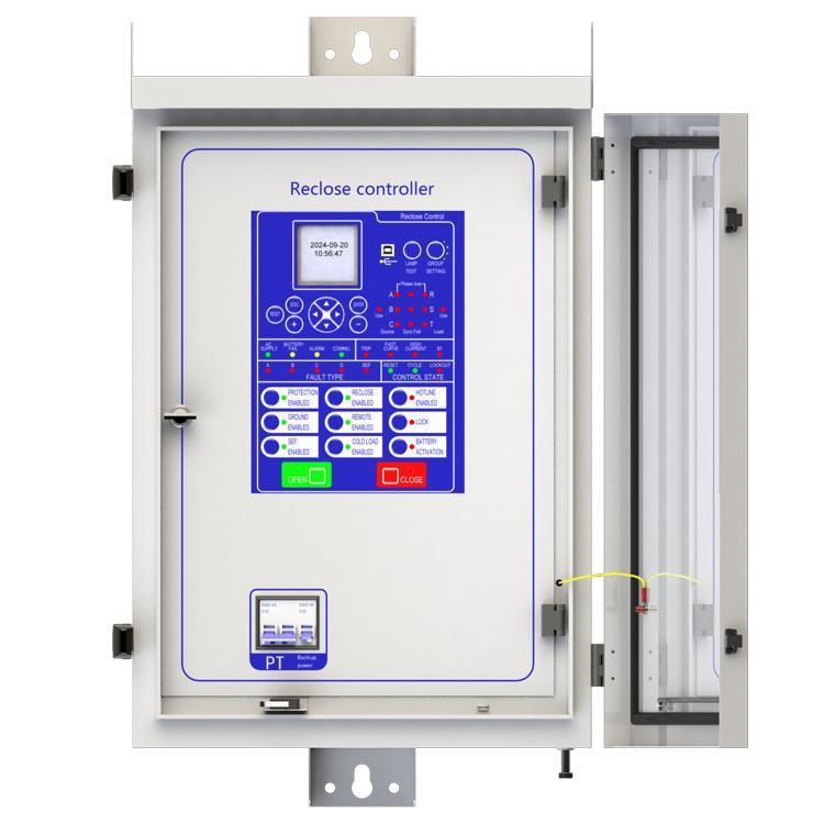
Use a high-performance PLC (Programmable Logic Controller) as the control center of the Automatic Circuit Recloser.
Rapidly clear transient faults to minimize outage time. In power systems, more than 70% of line faults are transient. If transient faults are treated the same as permanent faults, prolonged outages result. Therefore, an initial fast reclosing function has been added to Automatic Circuit Reclosers, which can clear transient faults within 0.3–1.0 seconds (settings vary depending on line conditions), greatly reducing outage duration for transient events.
Simultaneous lockout at both ends of the faulted section. Traditional circuit breakers can only lock out one end of a faulted line upon fault occurrence. In contrast, Automatic Circuit Reclosers can simultaneously isolate both ends of a permanently faulted section, preventing outages in non-faulted areas, shortening restoration time, reducing the number of reclosing attempts, and minimizing stress on the grid.
3.Application Principles of Automatic Circuit Reclosers in Distribution Networks
Operating Conditions: All faults should be given the opportunity to be treated as transient faults, avoiding misoperation due to inrush current. Lockout after tripping should occur only in the case of permanent faults.
Select and deploy Automatic Circuit Reclosers economically and reasonably based on load magnitude and line length.
Choose the rated current, breaking capacity, short-circuit current rating, and dynamic/thermal withstand current of the Automatic Circuit Recloser according to its installation location. The maximum short-circuit current rating should generally be above 16 kA to accommodate the continuously increasing grid capacity.
Properly coordinate protection settings, including trip current, number of reclosing attempts, and time-delay characteristics.
Coordinate between upstream and downstream Automatic Circuit Reclosers: the number of allowed fault current operations should decrease level by level, and the time delay for reclosing should increase level by level (typically set to 8 seconds per stage).