Relay mai yauwa na lokacin da ake amfani da su a cikin kawar da tushen gida. Daga binciken da suka da su, ana iya koyar da su zuwa uku nau'o'i: on-delay, off-delay, da combined on/off-delay relays. Idan an koyar da su, relay mai yauwa na on-delay su ne da ake amfani da shi mafi yawa da ke da shi a kasuwar samun kayan ado. Amma, akwai wasu relay mai yauwa na on-delay da suka da kungiyoyi masu hanyar yanayi kawai da ba suka da hanyar yanayi daban-daban, wanda ya haifar da aiki ga takamakon kayan ado da ke bukatar hanyar yanayi daban-daban.
Kuma, a lokacin da ake fadada takamakon kayan ado, ba da ake samun nau'o'i masu sabbin relay ya ba da abubuwa ga manyan enjinirin. Saboda haka, ana bukata amsa waɗannan masu aiki biyu: (1) Yadda ake iya kawo ƙarin aiki ga relay mai yauwa na on-delay da ba suka da hanyar yanayi daban-daban? (2) In ba da ake samun relay mai yauwa na off-delay, za a iya amfani da relay mai yauwa na on-delay a matsayin kofin? Don in amsa waɗannan tambayar, wannan rubutu ta bayyana karatu mai yauwa a cikin JSZ3A-B, ta yi misalai kan delayed-start circuits, delayed-stop circuits, da star-delta starting circuits, ta bayyana tushen aiki.
1. Tsarin Aiki da Nau'o'i Relay Mai Yauwa
Aiki ga relay mai yauwa suna da muhimmanci da hukumomin electromagnetism. Wani relay na musamman ya kunshi electromagnet da kofin da core mai zama. Idan ake ruwa kofi, ake shafi magnetic field wanda ya kula core mai zama, don haka ya kula ko kuka take. Lokacin da ake rarraba, ake seta lokaci da ake bukata a cikin relay.
2. Parametoru JSZ3A-B On-Delay Time Relay
JSZ3A-B time relay ya da kyauwa, kashi, tsari mai zurfi, kungiyoyi mai yawa, tsari mai sahihi, da tsari mai inganci, wanda ya ba shi daidai don systems mai kontrollo automatic da ke da shi a cikin machine tools da integrated equipment. Ya kunshi voltage control da aka zaba, AC 12–380 V ko DC 12–220 V. Kungiyoyi na lokaci na 1 s, 10 s, 60 s, da 6 min, wanda ake zaba a cikin switch selector a panel mai guje. Relay ya kunshi four sets of timed contacts: two normally open timed-closing contacts and two normally closed timed-opening contacts. Accuracy timing ya kai ≤0.5%, da temperature operating range -5°C to +40°C.
Idan an koyar da su, JSZ3A-B ya da terminals 8. Terminals 2 da 7 suka kofin; contacts 1–3 da 8–6 suka timed-closing (NO); contacts 1–4 da 8–5 suka timed-opening (NC). Users zai iya zaba contacts da suka fi dace a cikin design da suka bukata.
3. Applications of the JSZ3A-B On-Delay Time Relay
Time relays suna da amfani a cikin electrical control circuits da ke bukatar timed motor operations, including delayed start, delayed stop, and star-delta starting circuits.
3.1 Motor Delayed-Start Control Circuit Design
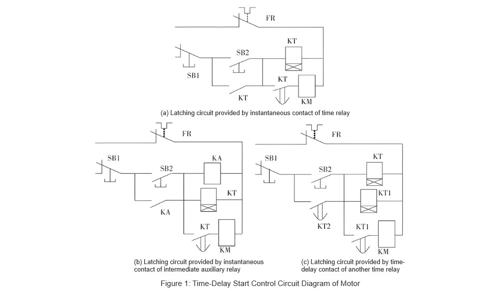
Motor delayed-start control circuit ta yi amfani da self-locking (latching) circuit. Ta yi amfani da timed contact normally open JSZ3A-B time relay ta kasa da coil contactor. Control circuit ta fito a Figure 1(a). A cikin Figure 1(a), control circuit ta kunshi time relay coil, timed normally open auxiliary contact, and instantaneous (immediate) contact. Amma, JSZ3A-B on-delay time relay ba suka da instantaneous contacts. A lokacin da ake fadada takamakon, idan an samu abin da ba suka da instantaneous contacts, za a iya amfani da hanyoyin biyu don in amsa.
3.1.1 Method One
Hanyar da ya fi dace da ke amfani da shi ita ce: using the normally open auxiliary contact of an intermediate relay or contactor to provide the motor self-locking path. Hanyar tana da muhimmanci ga beginners da ke son jin. The specific motor control circuit diagram ta fito a Figure 1(b). Additionally, replacing the intermediate auxiliary relay KA in the control circuit with another contactor KM can also meet the control requirements.
3.1.2 Method Two
Hanyar biyu ta yi amfani da timed contact normally open JSZ3A-B on-delay time relay ta kasa da self-locking path. Tana da damar a seta delay time ta zero. The corresponding motor control circuit diagram ta fito a Figure 1(c).
In addition to delayed-start control circuits, delayed-stop motor control circuits are also representative.
3.2 Motor Delayed-Stop Control Circuit Design
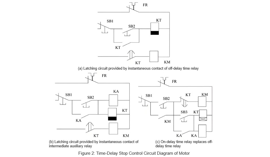
Off-delay time relays suna yi aiki wajen a yi immediate action a lokacin da ake ruwa coil, amma suna yi delay a lokacin da ake kusa. Wannan tsari ta da muhimmanci ga requirements for delayed-stop motor control. Saboda haka, using off-delay time relays makes it relatively straightforward to design a motor delayed-stop control circuit. The control circuit diagram is shown in Figure 2(a).
3.2.1 Off-Delay Time Relay Without Instantaneous Contacts
The circuit design illustrated in Figure 2(a) is fairly easy to understand. However, in practical applications, if an off-delay time relay does not include instantaneous contacts, intermediate auxiliary relays or the normally open auxiliary contacts of contactors can be used as substitutes for the instantaneous contacts of the time relay. The modified motor control circuit diagram is shown in Figure 2(b).
Operation process: Close the main circuit knife switch QS, press the start button SB2, and the intermediate relay KA and the time relay KT are energized. The normally open auxiliary contact of KA closes, achieving self-locking. The timed-off contact of KT closes immediately, energizing the contactor KM, allowing the motor to run normally. When pressing the stop button SB1, both KA and KT are de-energized. After the preset delay time elapses, the timed-off contact of KT opens, de-energizing the KM coil, causing the motor to stop.
3.2.2 Using On-Delay Time Relays Instead of Off-Delay Time Relays
If an off-delay time relay is unavailable, can an on-delay time relay be used as a substitute? Taking the JSZ3A-B on-delay time relay as an example, the circuit control diagram can be modified accordingly. The revised motor control circuit diagram is shown in Figure 2(c).
Operation process: Close the main circuit knife switch QS, press the start button SB2, and the contactor KM is energized. The normally open auxiliary contact of KM closes, achieving self-locking, allowing the motor to run normally. Pressing the start button SB3 energizes the intermediate relay KA and the time relay KT. The normally open auxiliary contact of KA closes, achieving self-locking. After the preset delay time elapses, the timed-on break contact of KT opens, de-energizing the KM coil, stopping the motor. Simultaneously, the self-locking contact of KM1 opens, de-energizing both the time relay KT and the intermediate relay KA.
This approach allows for a flexible solution when specific types of time relays are not available, ensuring continuous operation and reliability in motor control circuits.
3.3 Motor Star-Delta Starting Control Circuit Design
In industrial and agricultural production, to reduce the impact of motor startup on power voltage and other equipment, for motors with larger capacities that normally operate with three-phase stator windings connected in delta configuration, star-delta reduced voltage starting can be used to limit the starting current. During startup, the motor is first connected in a star configuration. When the motor speed reaches a certain value, the time relay activates, switching the connection to delta for normal operation.
3.3.1 Using Off-Delay Time Relays for Control Circuits
The control circuit can utilize the off-delay timed-off contacts of an off-delay time relay. The control circuit design is shown in Figure 3(a).
Operation process: Close the main circuit knife switch QS, press the start button SB2, and the intermediate relay KA, time relay KT, and contactor KM3 are simultaneously energized. The normally open auxiliary contact of KA closes, achieving self-locking. The timed-off contact of KT immediately closes, energizing the coil of contactor KM1 and de-energizing KM2, starting the motor in star configuration.
Since KM1 is energized, its normally closed contact opens, de-energizing the KT coil. After the preset delay time elapses, the timed-off contact of KT opens, de-energizing the KM1 coil. The normally closed contact of KM1 then closes, energizing the coils of contactor KM2 and time relay KT. The normally open contact of KM2 closes, achieving self-locking, while its normally closed contact opens, de-energizing KM3, disconnecting the star connection, and switching to delta configuration. Simultaneously, the timed-off contact of KT re-closes, re-energizing the KM1 coil, allowing the motor to run normally in delta configuration. Pressing the stop button SB1 de-energizes the KM1 coil, disconnecting the main circuit, and stopping the motor.
3.3.2 Using On-Delay Time Relays for Control Circuits
When the type of time relay is limited, the timed-off contacts of an on-delay time relay can replace the timed-off contacts of an off-delay time relay. The modified motor control circuit diagram using JSZ3A-B is shown in Figure 3(b).
Operation process: Close the main circuit knife switch QS, press the start button SB2, and the intermediate relay KA, time relay KT, contactor KM1, and KM3 are simultaneously energized, while KM2 is de-energized. The normally open auxiliary contact of KA closes, achieving self-locking, starting the motor in star configuration. After the preset delay time elapses, the timed-off contact of KT opens, de-energizing the KM1 coil.
The normally closed contact of KM1 then closes, energizing the KM2 coil. The normally open contact of KM2 closes, achieving self-locking, while its normally closed contact opens, de-energizing KM3, disconnecting the star connection, and switching to delta configuration. Simultaneously, the normally closed contact of KM3 closes, re-energizing the KM1 coil, allowing the motor to run normally in delta configuration. Pressing the stop button SB1 de-energizes the KM1 coil, disconnects the main circuit, and stops the motor.
Throughout the entire switching process in both control circuits mentioned above, the main contactor KM1 remains de-energized, providing effective safety protection for the motor.

4. Conclusion
This paper, using the JSZ3A-B as an example, presents the application of on-delay time relays without instantaneous contacts in motor delayed-start control circuits, delayed-stop control circuits, and star-delta starting circuits. It provides practical solutions for electrical circuit design when specific types of time relays are unavailable.


