Time relays are commonly used industrial control devices. Based on their timing characteristics, they can be classified into three types: on-delay, off-delay, and combined on/off-delay relays. Among these, on-delay time relays are the most widely used and readily available in the market. However, many on-delay relays have a limited number of contacts and only provide timed contacts without instantaneous ones, which poses inconvenience for electrical control circuit designs requiring immediate response contacts.
Additionally, during equipment circuit design, the unavailability of a specific relay type often creates difficulties for engineers. Therefore, two key issues need to be addressed: (1) How to expand the application range of on-delay time relays that lack instantaneous contacts? (2) Can on-delay time relays be used as substitutes for off-delay relays when the latter are unavailable? To address these questions, this paper presents a systematic study based on the JSZ3A-B time relay, using delayed-start circuits, delayed-stop circuits, and star-delta starting circuits as examples, providing practical references.
1. Working Principle and Types of Time Relays
The operation of time relays is primarily based on electromagnetic attraction and release principles. A typical relay consists of an electromagnet with a coil and a movable iron core. When the coil is energized, the generated magnetic field attracts the movable core, thereby closing or opening a circuit. The required time delay is set by adjusting a knob or dial on the relay.
2. Parameters of the JSZ3A-B On-Delay Time Relay
The JSZ3A-B time relay features compact size, light weight, high structural integrity, wide timing range, high timing accuracy, excellent reliability, and long service life, making it suitable for automatic control systems in machine tools and integrated equipment. It offers multiple rated control voltage options, selectable from AC 12–380 V or DC 12–220 V. The timing range includes 1 s, 10 s, 60 s, and 6 min, switchable via a selector switch on the front panel. The relay provides four sets of timed contacts: two normally open timed-closing contacts and two normally closed timed-opening contacts. Timing accuracy is ≤0.5%, and the operating temperature range is -5°C to +40°C.
As an on-delay relay, the JSZ3A-B has eight terminals. Terminals 2 and 7 connect to the power supply; contacts 1–3 and 8–6 are timed-closing (NO); contacts 1–4 and 8–5 are timed-opening (NC). Users can select appropriate contacts for circuit design according to their needs.
3. Applications of the JSZ3A-B On-Delay Time Relay
Time relays are widely used in electrical control circuits requiring timed motor operations, including delayed start, delayed stop, and star-delta starting circuits.
3.1 Motor Delayed-Start Control Circuit Design
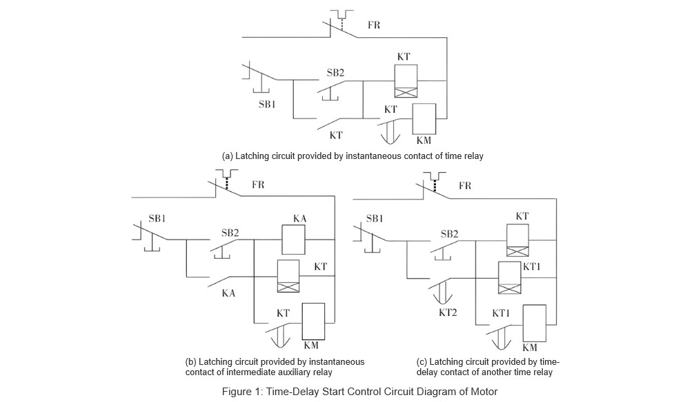
The motor delayed-start control circuit is based on a self-locking (latching) circuit. It achieves time-delayed motor control by connecting the normally open timed contact of the JSZ3A-B time relay in series with the contactor coil. The control circuit is shown in Figure 1(a). As shown in Figure 1(a), the control circuit includes the time relay coil, a timed normally open auxiliary contact, and an instantaneous (immediate) contact. However, the JSZ3A-B on-delay time relay only provides timed contacts and lacks instantaneous ones. When designing practical circuits, if a similar issue arises, the following two methods can be used to resolve it.
3.1.1 Method One
The first method is the simplest and most commonly used: using the normally open auxiliary contact of an intermediate relay or contactor to provide the motor self-locking path. This method is easy for beginners to understand and implement. The specific motor control circuit diagram is shown in Figure 1(b). Additionally, replacing the intermediate auxiliary relay KA in the control circuit with another contactor KM can also meet the control requirements.
3.1.2 Method Two
The second method uses the normally open timed contact of another JSZ3A-B on-delay time relay to provide the self-locking path. This is achieved simply by setting its time delay to zero. The corresponding motor control circuit diagram is shown in Figure 1(c).
In addition to delayed-start control circuits, delayed-stop motor control circuits are also representative.
3.2 Motor Delayed-Stop Control Circuit Design
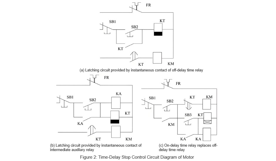
Off-delay time relays operate such that their contacts act immediately upon coil energization without any delay, but they reset with a delay when the coil is de-energized. This characteristic aligns perfectly with the requirements for delayed-stop motor control. Therefore, using off-delay time relays makes it relatively straightforward to design a motor delayed-stop control circuit. The control circuit diagram is shown in Figure 2(a).
3.2.1 Off-Delay Time Relay Without Instantaneous Contacts
The circuit design illustrated in Figure 2(a) is fairly easy to understand. However, in practical applications, if an off-delay time relay does not include instantaneous contacts, intermediate auxiliary relays or the normally open auxiliary contacts of contactors can be used as substitutes for the instantaneous contacts of the time relay. The modified motor control circuit diagram is shown in Figure 2(b).
Operation process: Close the main circuit knife switch QS, press the start button SB2, and the intermediate relay KA and the time relay KT are energized. The normally open auxiliary contact of KA closes, achieving self-locking. The timed-off contact of KT closes immediately, energizing the contactor KM, allowing the motor to run normally. When pressing the stop button SB1, both KA and KT are de-energized. After the preset delay time elapses, the timed-off contact of KT opens, de-energizing the KM coil, causing the motor to stop.
3.2.2 Using On-Delay Time Relays Instead of Off-Delay Time Relays
If an off-delay time relay is unavailable, can an on-delay time relay be used as a substitute? Taking the JSZ3A-B on-delay time relay as an example, the circuit control diagram can be modified accordingly. The revised motor control circuit diagram is shown in Figure 2(c).
Operation process: Close the main circuit knife switch QS, press the start button SB2, and the contactor KM is energized. The normally open auxiliary contact of KM closes, achieving self-locking, allowing the motor to run normally. Pressing the start button SB3 energizes the intermediate relay KA and the time relay KT. The normally open auxiliary contact of KA closes, achieving self-locking. After the preset delay time elapses, the timed-on break contact of KT opens, de-energizing the KM coil, stopping the motor. Simultaneously, the self-locking contact of KM1 opens, de-energizing both the time relay KT and the intermediate relay KA.
This approach allows for a flexible solution when specific types of time relays are not available, ensuring continuous operation and reliability in motor control circuits.
3.3 Motor Star-Delta Starting Control Circuit Design
In industrial and agricultural production, to reduce the impact of motor startup on power voltage and other equipment, for motors with larger capacities that normally operate with three-phase stator windings connected in delta configuration, star-delta reduced voltage starting can be used to limit the starting current. During startup, the motor is first connected in a star configuration. When the motor speed reaches a certain value, the time relay activates, switching the connection to delta for normal operation.
3.3.1 Using Off-Delay Time Relays for Control Circuits
The control circuit can utilize the off-delay timed-off contacts of an off-delay time relay. The control circuit design is shown in Figure 3(a).
Operation process: Close the main circuit knife switch QS, press the start button SB2, and the intermediate relay KA, time relay KT, and contactor KM3 are simultaneously energized. The normally open auxiliary contact of KA closes, achieving self-locking. The timed-off contact of KT immediately closes, energizing the coil of contactor KM1 and de-energizing KM2, starting the motor in star configuration.
Since KM1 is energized, its normally closed contact opens, de-energizing the KT coil. After the preset delay time elapses, the timed-off contact of KT opens, de-energizing the KM1 coil. The normally closed contact of KM1 then closes, energizing the coils of contactor KM2 and time relay KT. The normally open contact of KM2 closes, achieving self-locking, while its normally closed contact opens, de-energizing KM3, disconnecting the star connection, and switching to delta configuration. Simultaneously, the timed-off contact of KT re-closes, re-energizing the KM1 coil, allowing the motor to run normally in delta configuration. Pressing the stop button SB1 de-energizes the KM1 coil, disconnecting the main circuit, and stopping the motor.
3.3.2 Using On-Delay Time Relays for Control Circuits
When the type of time relay is limited, the timed-off contacts of an on-delay time relay can replace the timed-off contacts of an off-delay time relay. The modified motor control circuit diagram using JSZ3A-B is shown in Figure 3(b).
Operation process: Close the main circuit knife switch QS, press the start button SB2, and the intermediate relay KA, time relay KT, contactor KM1, and KM3 are simultaneously energized, while KM2 is de-energized. The normally open auxiliary contact of KA closes, achieving self-locking, starting the motor in star configuration. After the preset delay time elapses, the timed-off contact of KT opens, de-energizing the KM1 coil.
The normally closed contact of KM1 then closes, energizing the KM2 coil. The normally open contact of KM2 closes, achieving self-locking, while its normally closed contact opens, de-energizing KM3, disconnecting the star connection, and switching to delta configuration. Simultaneously, the normally closed contact of KM3 closes, re-energizing the KM1 coil, allowing the motor to run normally in delta configuration. Pressing the stop button SB1 de-energizes the KM1 coil, disconnects the main circuit, and stops the motor.
Throughout the entire switching process in both control circuits mentioned above, the main contactor KM1 remains de-energized, providing effective safety protection for the motor.

4. Conclusion
This paper, using the JSZ3A-B as an example, presents the application of on-delay time relays without instantaneous contacts in motor delayed-start control circuits, delayed-stop control circuits, and star-delta starting circuits. It provides practical solutions for electrical circuit design when specific types of time relays are unavailable.


