Time relay applications & wiring methods for optimizing control circuits, improving accuracy and reliability in real-world systems.

As an electrical component capable of achieving time-delay control, time relays are widely used in various circuit systems. Correctly understanding and mastering the wiring methods of time relays is essential for electrical engineers and electronics enthusiasts. This article presents detailed wiring diagrams to explain the applications and wiring methods of two common types—on-delay and off-delay time relays—in practical circuits.
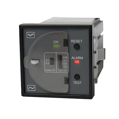
1. On-Delay Time Relay
1. Wiring Diagram Explanation
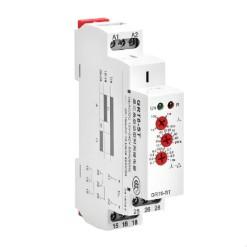
A typical on-delay time relay wiring diagram includes the coil power supply and switching contacts. For example, pins 2 and 7 are the coil power input terminals; if using DC power, correct polarity must be observed. Terminals 1, 3, 4 and 5, 6, 8 represent two sets of changeover contacts. Contacts 1 and 4 are normally closed (NC), remaining closed until the preset delay time is reached. At that point, 1 and 4 open, while 1 and 3 close. Pin 8 is the common terminal, forming a normally open (NO) contact with pin 6 (closes after delay) and a normally closed (NC) contact with pin 5 (opens after delay).

1.2 Practical Application Example
(1) Delayed Turn-On: In applications requiring delayed activation, the on-delay time relay’s changeover contact can be used. When an input signal is applied, after the preset delay time, the contact changes state, thereby turning on the corresponding circuit.

(2) Delayed Turn-Off: Similarly, to achieve a delayed turn-off function, the wiring of an on-delay time relay can be adjusted accordingly. After the input signal disappears, the contacts open after a preset delay time, thereby disconnecting the circuit.
2. Off-Delay Time Relay
2.1 Wiring Diagram Explanation
The wiring diagram of an off-delay time relay differs from that of the on-delay type. Using a specific model as an example, pins 2 and 7 are the coil power supply terminals. Pins 3 and 4 are external reset signal terminals; a signal can be connected here to interrupt the delay function if needed, otherwise they can be left unconnected. Terminals 5, 6, and 8 form one set of changeover contacts, where 5 and 8 are normally closed (NC). When the relay coil is energized, contacts 5 and 8 open instantly. After the coil is de-energized, they close again after the preset delay time. Contacts 6 and 8 are normally open (NO), closing instantly when the coil is energized and returning to open state after a delay once the coil is de-energized.

2.2 Practical Application Examples
Off-delay time relays are often used in scenarios where the output state needs to be maintained for a period of time after the input signal disappears. For instance, in elevator door control systems, an off-delay time relay can be utilized to achieve a delayed door closing function after the door closing signal has disappeared. Additionally, in the reset control of safety equipment, this type of time relay can also be used to implement a delayed reset function.
3. Summary
Through this article, we can see the important role time relays play in circuit control. Different types of time relays have distinct operating principles and application scenarios, and a correct understanding of their use is essential for improving the stability and reliability of circuit systems. Meanwhile, mastering time relay wiring methods is a fundamental skill essential for both electrical engineers and electronics enthusiasts.