
Որքան գլոբալ էներգետիկայի կրիզիսը խուսափում է և միջավայրային անհանդարձությունը ավելի ծանրացնում է, աշխարհի կառավարությունները ավելի շատ կապակցություն են կայացնում նոր էներգետիկ էլեկտրաէներգիայի հետազոտությունների և զարգացման համար: Տունական օգտագործման համար սոլային կառուցվածքները, որոնք են ՊՎ ընկերության հաջորդ փուլի կարևոր ուղղությունները, ավելի շատ հարմար են դառնում: Այնուամենայնիվ, ՊՎ կոմպոնենտների էլեկտրաէներգիայի արտադրության հաճախակի փոփոխությունները և էներգետիկ պահեստավորման միավորների ինտեգրացիայի համար ռեալիստական համակարգը կարող է խնդրահարույց դառնալ տունական էլեկտրաէներգիայի օգտագործման համար: Այսպիսով, համակարգի միավորների միջև կայուն էներգետիկ հոսքի համակցումը և համարժեք աշխատանքի ապահովումը պահանջում է էներգետիկ հանդերձության ստրատեգիա, որը կարող է հավասարակշռել առաջարկությունները և պահանջները: Այս հոդվածը, հիմնվելով տունական ՊՎ-էներգետիկ պահեստավորման համակարգերի վրա, հետազոտում է էներգետիկ հանդերձությունը կայուն աշխատանքի համար և տալիս է գործնական կարմիր էներգետիկ կիրառումների համար տեսական հիմք:
1 Սիստեմայի Կառուցվածքի և Էներգետիկ Հանդերձության Ալգորիթմի Անալիզ
Հետազոտվող տունական ՊՎ-էներգետիկ պահեստավորման համակարգի (գծագիր 1) տոպոլոգիան ներառում է ՊՎ մոդուլներ, լիթիում-իոնային պահեստավորման բատարիաներ, էլեկտրաէներգիայի կոնվերտերներ, ցանց և օգտագործողի բեռնավորումները: ՊՎ մոդուլների արտադրությունը հանդիսանում է ընդհանուր DC բուս լարումը Բոոստ կոնվերտերի միջոցով: Լիթիում-իոնային բատարիաները կապված են այս բուսին Բակ-Բոոստ կոնվերտերի միջոցով: Դիսկ բուսը հետագա էլեկտրաէներգիան ներկայացնում է միաֆազ ցանցի կամ բեռնավորումների համար լրիվ միջոցով ինվերտերի միջոցով:
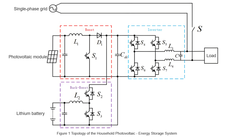
Սիստեմը նախապայմանավորում է "ինքնագեներացիոն և ինքնապատրաստում": ՊՎ մոդուլների արտադրությունը, որպես գլխավոր էներգետիկ աղբյուր, սկզբում բավարարում է օգտագործողի բեռնավորումներին: ՊՎ էներգիայի ավելացումը/պակասը հավասարակշռվում է լիթիում-իոնային բատարիաներով (երկրորդական աղբյուր); եթե և ՊՎ և բատարիաները հասնում են սահմաններին, ցանցը (երրորդ աղբյուր) ապահովում է կայուն առաջարկությունը:
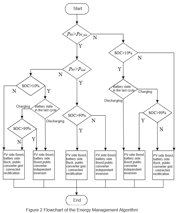
ՊՎ արտադրության համար, բատարիայի SOC-ի և լիցքավորման-լիցքային էլեկտրաէներգիայի համար: Եթե PPV < PPV-min}, Բոոստ կոնվերտերը կանգ է դնում (չկա էլեկտրաէներգիայի արտադրություն): Այլimentiwise, it operates. Batteries stop charging when SOC > 90% and discharging when SOC < 10%. Pbat adjusts dynamically with PPV and Pload, ranging from 0 to max battery charging power. To avoid frequent charge-discharge oscillations, the next cycle's state depends on the previous cycle's battery status, preventing frequent system mode switches.
Based on this, an energy management algorithm for household PV-storage systems is proposed, as shown in Figure 2.
2 Analysis of System Operation Modes and Energy Flow
Guided by the energy management algorithm, the system’s operation splits into independent and grid - connected modes, each further subdivided as follows:
2.1 Independent Operation (By Main Power)
Two sub - modes exist, defined by the power source controlling the DC bus:
2. 2 Grid - Connected Operation (By Inverter State)
Split by whether the inverter is in inversion or rectification:
2.3 Mode Boundaries & Coordination
The 4 sub - modes’ trigger conditions and equipment coordination are detailed in Table 1 (to be added). Through dynamic switching of “PV - battery - grid” power and adaptive control of Boost/Buck - Boost converters and the inverter, the system enables efficient energy flow in “generation - storage - consumption”, covering all household power needs (off - grid, grid - connected, emergency, etc.).
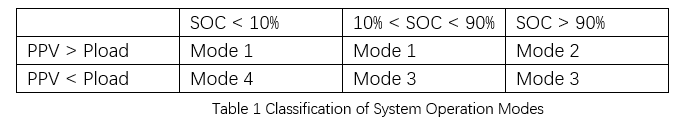
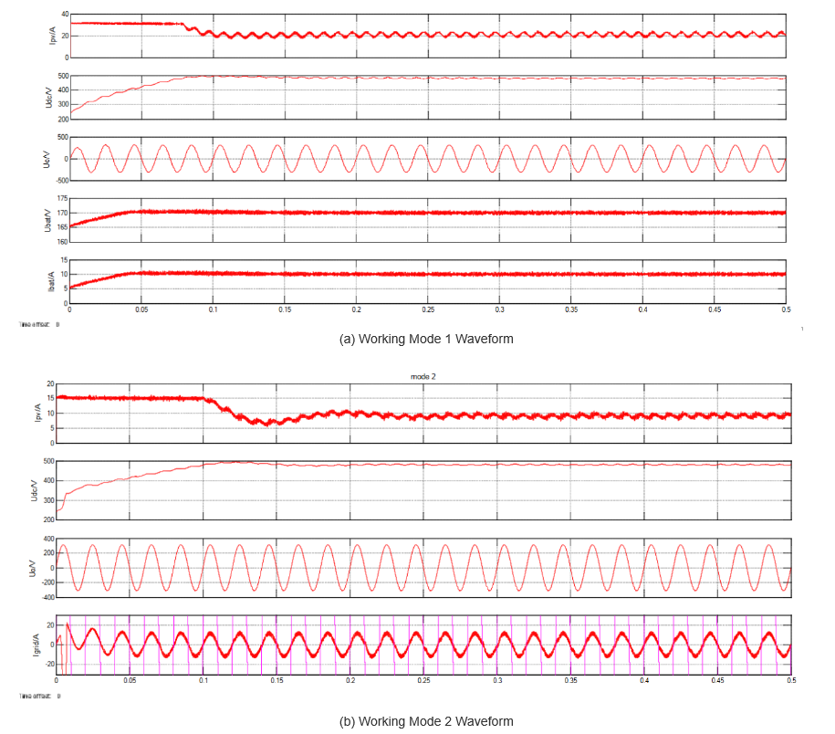
Figure 3(a) shows the waveform for Mode 1: PV output = 4.8 kW, load = 3 kW. The PV module outputs 240 Vdc; the Boost converter stabilizes the DC bus at 480 Vdc. The inverter runs in independent inversion (220 Vac for loads), and the Buck - Boost works in Buck mode (1.8 kW to charge the battery). Waveforms (top to bottom): PV output current, DC bus voltage, inverter output voltage, and battery charging current.
Figure 3(b) corresponds to Mode 2: PV output = 5 kW (battery full, so Buck - Boost is off). Load = 3 kW; the inverter uses grid - connected inversion to keep the DC bus at 480 Vdc, feeding excess energy to the grid (9 A, synchronized with grid voltage). Waveforms: PV output current, DC bus voltage, inverter output voltage, and grid - connected current.
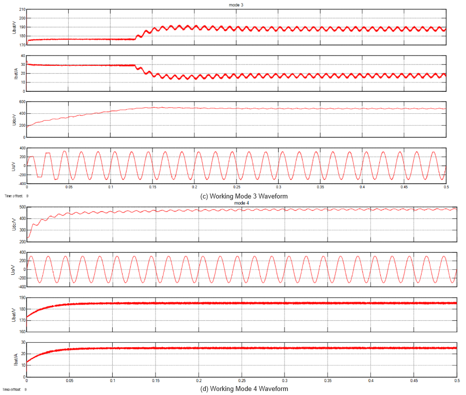
Figure 3(c) shows Mode 3: The PV module hits limits (no output, Boost off). The energy storage unit powers the system; the Buck - Boost runs in Boost mode (DC bus = 480 Vdc). The inverter uses independent inversion (220 Vac for 3 - kW loads). Waveforms: Battery discharge current, DC bus voltage, and inverter output voltage.Figure 3(d) presents Mode 4: Both PV and energy storage hit limits (no output). The grid powers loads (3 kW) and charges the battery; the inverter uses grid - connected rectification (DC bus = 480 Vdc).
3. Conclusion (Street - lamp Maintenance)
Current urban street - lamp maintenance has shortcomings. To improve, focus on four areas:
These steps will enhance street - lamp management efficiency, supporting smart city operations and green development.


