• Product
  • Suppliers
  • Manufacturers
  • Solutions
  • Free tools
  • Knowledges
  • Experts
  • Communities
Search


Household PV-ESS Energy Management Simulation Study

Dyson
Dyson
Field: Electrical Standards
China

As the global energy crisis worsens and environmental pollution grows more severe, governments worldwide are boosting support for R&D in new energy power generation. The household use of solar distributed generation, a key next - phase direction for the PV industry, has gained increasing attention. However, issues like power output fluctuations of PV components and the rationality of energy storage unit integration can seriously affect household electricity use. Thus, to coordinate stable energy flow between system units and ensure smooth operation, an energy management strategy is needed to balance supply and demand. This paper, based on household PV - energy storage systems, studies energy management to enable stable operation and provide a theoretical basis for practical clean energy applications.

1 Analysis of System Structure and Energy Management Algorithm

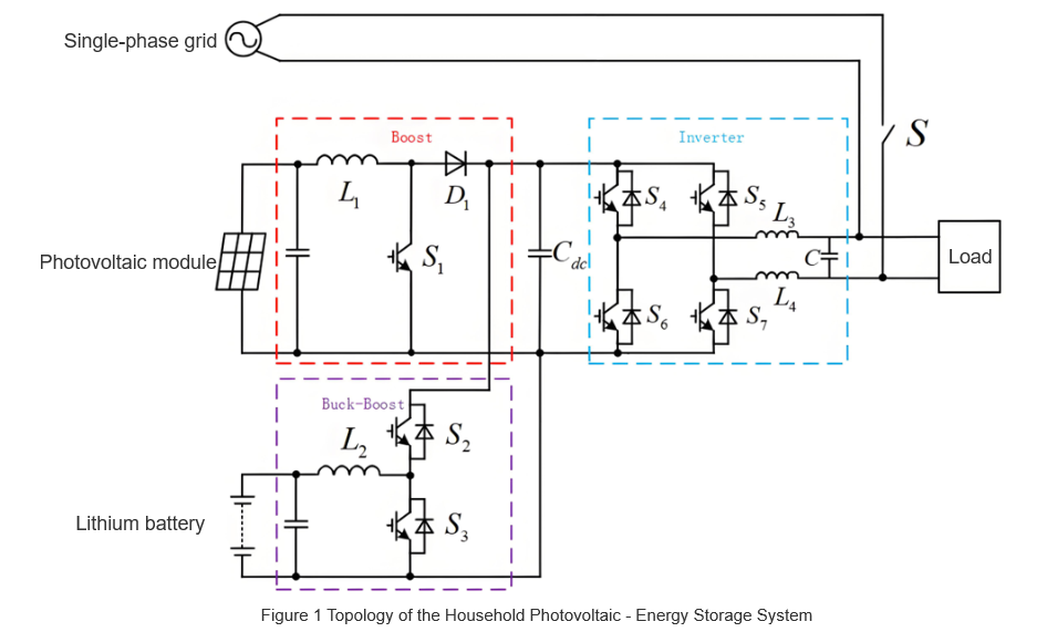
The topology of the studied household PV - energy storage system (Figure 1) comprises PV modules, lithium - ion storage batteries, power converters, the grid, and user loads. PV module output forms a common DC bus voltage via a Boost converter. Lithium - ion batteries connect to this bus through a Buck - Boost converter. The DC bus then feeds power into the single - phase grid or supplies loads independently via a full - bridge inverter.

The system prioritizes "self-generation and self-consumption". PV module output, as the primary power source, first meets user loads. Surplus/deficit PV power is balanced by lithium batteries (secondary source); if both PV and batteries hit limits, the grid (tertiary source) ensures stable supply.

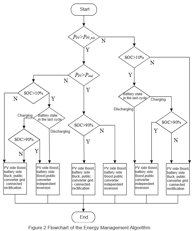
For PV output, battery SOC, and charge-discharge power: If PPV < PPV-min}\), the Boost converter shuts down (no power output); otherwise, it operates. Batteries stop charging when SOC > 90% and discharging when SOC < 10%. Pbat adjusts dynamically with PPV and Pload, ranging from 0 to max battery charging power. To avoid frequent charge-discharge oscillations, the next cycle's state depends on the previous cycle's battery status, preventing frequent system mode switches.

Based on this, an energy management algorithm for household PV-storage systems is proposed, as shown in Figure 2.

2 Analysis of System Operation Modes and Energy Flow

Guided by the energy management algorithm, the system&rsquo;s operation splits into independent and grid - connected modes, each further subdivided as follows:

2.1 Independent Operation (By Main Power)

Two sub - modes exist, defined by the power source controlling the DC bus:

  • PV - Driven Mode

    • PV as main power; Boost runs in CV mode to stabilize DC bus.

    • Inverter works in independent inversion for load supply.

    • If PV power > load + battery charge power, Buck - Boost uses Buck mode to charge the battery; else, Buck - Boost idles.

    • Trigger: PV output > load, battery not full.

    • Logic:

    • Battery - Driven Mode

      • Battery as main power; Buck - Boost runs in Boost mode to stabilize DC bus.

      • Inverter uses independent inversion for load supply.

      • If PV has weak output, Boost operates in MPPT mode; if no PV output, Boost idles.

      • Trigger: PV output < load, battery has remaining capacity.

      • Logic:

    2. 2 Grid - Connected Operation (By Inverter State)

    Split by whether the inverter is in inversion or rectification:

    • Grid - Connected Inversion

      • Inverter uses grid - connected inversion to stabilize DC bus, feeding excess energy to the grid.

      • Boost runs in MPPT mode to maximize power output.

      • Buck - Boost idles.

      • Trigger: PV output > load, battery fully charged.

      • Logic:

    • Grid - Connected Rectification

      • Inverter uses grid - connected rectification to stabilize DC bus.

      • Buck - Boost runs in Buck mode to charge the battery until SOC > 90%.

      • If PV has weak output, Boost uses MPPT mode; if no PV output, Boost idles.

      • Trigger: PV output < load, battery insufficient (both primary/secondary power hit limits).

      • Logic:

    2.3 Mode Boundaries & Coordination

    The 4 sub - modes&rsquo; trigger conditions and equipment coordination are detailed in Table 1 (to be added). Through dynamic switching of &ldquo;PV - battery - grid&rdquo; power and adaptive control of Boost/Buck - Boost converters and the inverter, the system enables efficient energy flow in &ldquo;generation - storage - consumption&rdquo;, covering all household power needs (off - grid, grid - connected, emergency, etc.).


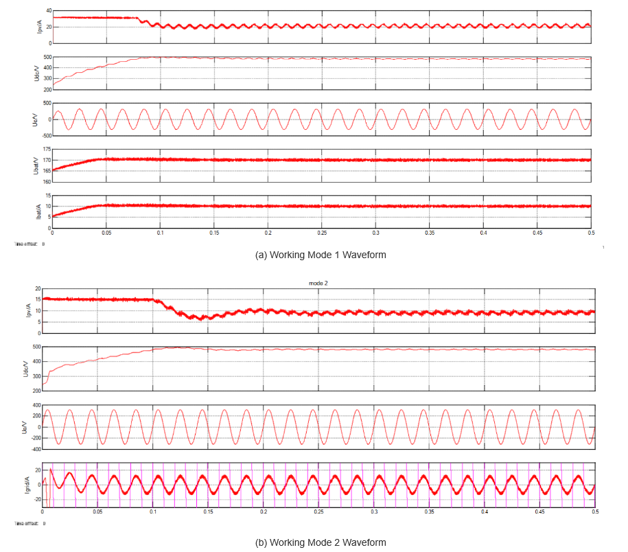
    Figure 3(a) shows the waveform for Mode 1: PV output = 4.8 kW, load = 3 kW. The PV module outputs 240 Vdc; the Boost converter stabilizes the DC bus at 480 Vdc. The inverter runs in independent inversion (220 Vac for loads), and the Buck - Boost works in Buck mode (1.8 kW to charge the battery). Waveforms (top to bottom): PV output current, DC bus voltage, inverter output voltage, and battery charging current.

    Figure 3(b) corresponds to Mode 2: PV output = 5 kW (battery full, so Buck - Boost is off). Load = 3 kW; the inverter uses grid - connected inversion to keep the DC bus at 480 Vdc, feeding excess energy to the grid (9 A, synchronized with grid voltage). Waveforms: PV output current, DC bus voltage, inverter output voltage, and grid - connected current.

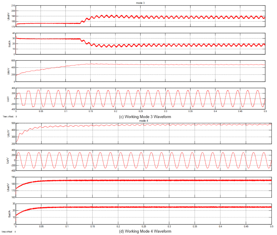
    Figure 3(c) shows Mode 3: The PV module hits limits (no output, Boost off). The energy storage unit powers the system; the Buck - Boost runs in Boost mode (DC bus = 480 Vdc). The inverter uses independent inversion (220 Vac for 3 - kW loads). Waveforms: Battery discharge current, DC bus voltage, and inverter output voltage.Figure 3(d) presents Mode 4: Both PV and energy storage hit limits (no output). The grid powers loads (3 kW) and charges the battery; the inverter uses grid - connected rectification (DC bus = 480 Vdc).

    3. Conclusion (Street - lamp Maintenance)

    Current urban street - lamp maintenance has shortcomings. To improve, focus on four areas:

    • Broaden funding for sufficient maintenance budgets.

    • Strengthen publicity/inspections to resolve issues timely.

    • Promote green lighting to cut costs and boost efficiency.

    • Establish standardized management systems for uniform operations.

    These steps will enhance street - lamp management efficiency, supporting smart city operations and green development.

    Give a tip and encourage the author!
    Recommended
    Minimum Operating Voltage for Vacuum Circuit Breakers
    Minimum Operating Voltage for Vacuum Circuit Breakers
    Minimum Operating Voltage for Trip and Close Operations in Vacuum Circuit Breakers1. IntroductionWhen you hear the term "vacuum circuit breaker," it might sound unfamiliar. But if we say "circuit breaker" or "power switch," most people will know what it means. In fact, vacuum circuit breakers are key components in modern power systems, responsible for protecting circuits from damage. Today, let's explore an important concept — the minimum operating voltage for trip and close operations.Though it
    Dyson
    10/18/2025
    Efficient Wind-PV Hybrid System Optimization with Storage
    Efficient Wind-PV Hybrid System Optimization with Storage
    1. Analysis of Wind and Solar Photovoltaic Power Generation CharacteristicsAnalyzing the characteristics of wind and solar photovoltaic (PV) power generation is fundamental to designing a complementary hybrid system. Statistical analysis of annual wind speed and solar irradiance data for a specific region reveals that wind resources exhibit seasonal variation, with higher wind speeds in winter and spring and lower speeds in summer and autumn. Wind power generation is proportional to the cube of
    Dyson
    10/15/2025
    Wind-Solar Hybrid Powered IoT System for Real-Time Water Pipeline Monitoring
    Wind-Solar Hybrid Powered IoT System for Real-Time Water Pipeline Monitoring
    I. Current Status and Existing ProblemsCurrently, water supply companies have extensive networks of water pipelines laid underground across urban and rural areas. Real-time monitoring of pipeline operation data is essential for effective command and control of water production and distribution. As a result, numerous data monitoring stations must be established along the pipelines. However, stable and reliable power sources near these pipelines are rarely available. Even when power is accessible,
    Dyson
    10/14/2025
    How to Build an AGV-Based Intelligent Warehouse System
    How to Build an AGV-Based Intelligent Warehouse System
    Intelligent Warehouse Logistics System Based on AGVWith the rapid development of the logistics industry, growing land scarcity, and rising labor costs, warehouses—serving as key logistics hubs—are facing significant challenges. As warehouses become larger, operational frequencies increase, information complexity grows, and order-picking tasks become more demanding, achieving low error rates and reduced labor costs while improving overall storage efficiency has become a primary goal for the wareh
    Dyson
    10/08/2025
    Send inquiry
    Download
    Get the IEE Business Application
    Use the IEE-Business app to find equipment, obtain solutions, connect with experts, and participate in industry collaboration anytime, anywhere—fully supporting the development of your power projects and business.