1 Live Testing Analysis
Detection of Issues through Live Testing
In October of a certain year, during live partial discharge (PD) testing on 10kV ring main units (RMUs) under our jurisdiction, the maintenance and testing team observed significantly elevated signal amplitudes in several units (Transient Earth Voltage (TEV) readings around 18 dB, and ultrasonic readings around 20 dB). Most of these units were from the same manufacturer. Consequently, a unified test was conducted on 15 RMUs from this manufacturer across the network, revealing similar discharge phenomena in 7 units.
Visual inspection through observation windows showed obvious tracking marks on the cable terminations and clear signs of burning on the T-connectors. Upon disassembling the cable terminations, severe discharge damage was found in some units. Tracking and arcing marks were visible on the inner wall of the plug, the main body of the surge arrester, the surface of the epoxy bushing, and the surface of the plug cap. Furthermore, the interface between the plug body and the cap could be easily pried apart by hand, indicating insufficient clamping force. This allowed moisture ingress, leading to corrosion of metal components and reduced insulation strength at the interface, resulting in varying degrees of surface tracking. After replacing the affected components with qualified parts, follow-up retesting was conducted on these RMUs. The partial discharge measurements have since remained within normal ranges.
2 Summary of Testing Experience
Determining whether an RMU has partial discharge requires a comprehensive assessment based on "listening," "smelling," "observing," and "measuring." Routine testing generally follows these steps:
Preparation before Testing: Ensure the handheld PD detector is self-checked and functioning properly. Prepare a flashlight and relevant equipment documentation. Inspect the environment around the RMU to ensure safety for personnel and equipment before proceeding. Verify that the equipment name and number match the system records, and confirm that the labeling on each cabinet is accurate.
Preliminary Diagnosis ("Listen," "Smell," "Observe"): Check if the RMU’s gas pressure is normal. Before measurement, listen for any abnormal sounds from the RMU; if distinct discharge noises are heard, immediately move away from the equipment and promptly report to the equipment manager for emergency handling. Before opening the cabinet door, smell for any unusual odors inside; a noticeable burnt smell indicates the unit should be prioritized for testing. If the RMU has an observation window, use a flashlight to inspect the interior. Discharge on the cable termination typically forms tree-like discharge traces on the T-connector extending to the grounding point, and the insulating plug may show white, melted burn marks.
Testing Procedure:
Measure Background Value: The background value refers to the signal measured on the metal door of the 10kV high-voltage room. Since high-frequency signals from partial discharge are electromagnetic waves that propagate in all directions, transient earth voltages can be induced on grounded metal surfaces even in non-energized areas. Measuring the background value before testing the RMU provides a rough indication of the overall PD condition in the high-voltage room.
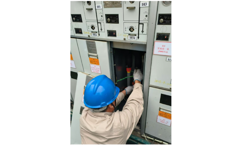
TEV Measurement: Place the sensor tightly against the metal surface of the cabinet and pay attention to the measurement position. Due to the short wavelength of high-frequency PD signals, attenuation is rapid—shorter wavelengths decay faster. On the measuring instrument, this manifests as a signal amplitude that decreases from strong to weak, which can be used to help locate the source of the discharge.
Ultrasonic Measurement: Conduct measurements at the gaps between cabinet doors to enhance sensitivity to airborne sound waves.
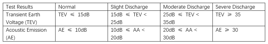
Result Evaluation: Analyze the measurement data and draw conclusions based on the judgment criteria specified in the Shenzhen Bureau RMU Partial Discharge Testing Work Instruction. Refer to Table 1 for the RMU partial discharge testing evaluation standards.