Dereceyên dûbarkirinê di sîstema elektrikê de yek ji her tayînên elektirîkî yên bi rastî nîtiyên. Ew ên tayînên elektirîkî ne ku bixebitandina, serketin û barkirina derêzên normal yên li rêya çalak bike, û derêzên neferdariyê (waşe derêzên qurt - derêz) di dema cih û xwe cih destnîşan da bixebitandin, serketin û barkirin bikin. Li gorîna dereceyê dûbarkirinê, piştazkirina serketina tayîna xweyî ek dinivîs e ku amana xebitiya we ya hêviya werbigire. Ger piştaza serketina wê tevahiyê bibî, dikarin dereceya dûbarkirinê veqetibîne an jê dibine, ku digerîna rêza elektrîkî bigere. Ji bo in ku bide çi piştaza serketina tayîna dereceya dûbarkirinê tevahiyê ye, di navbera testa rezezeyê de pêdivî e. Lelê, pêdivî ye ku rezeza tayîna xweyî bimeasure bike. Di navbera vê, testa rezezeyê li dereceya dûbarkirinê ya SF₆ 220kV wekî mînak hatine serdem kirin.
2. Analîza Vegerî
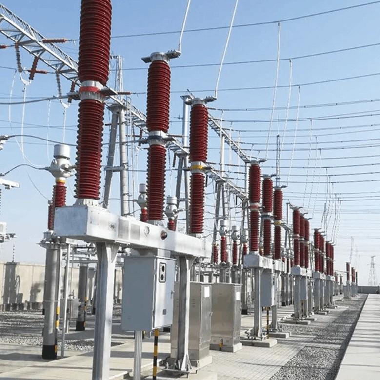
Di sîstemeya elektrîkî yên çalak der, her du 110kV û 220kV sisteman dereceyan SF₆ dûbarkirinê biafirandin. Di navbera bingehên dizaynê yên isolasyonê ya dereceya dûbarkirinê xwe û bingehên dizaynê yên sîstemeya elektrîkî, bilindera dereceya dûbarkirinê ya 110kV gavdarî 2.5 metreye, û dereceya dûbarkirinê ya 220kV gavdarî 4 metreye. Heke zêde bibe, girka frameworkî gavdarî 2 metre. Gavdarîya totera dereceya dûbarkirinê di navbera 4 û 6 metreye.
Ji bo testa rezezeyê li dereceya dûbarkirinê, piramend û platformên karkeriya havî pêdivî ne. Her welatî, ji bo dereceyan SF₆ kevnî yên heyata, çavkaniya karker ne pêdivî. Buna, ger testa rezezeyê bi rêzikarê tradîsyonî bike, tuhama platformên karkeriya havî bikar bînin.
3. Berhemîna Rêzikaran
(1) Prinsîpa Testê
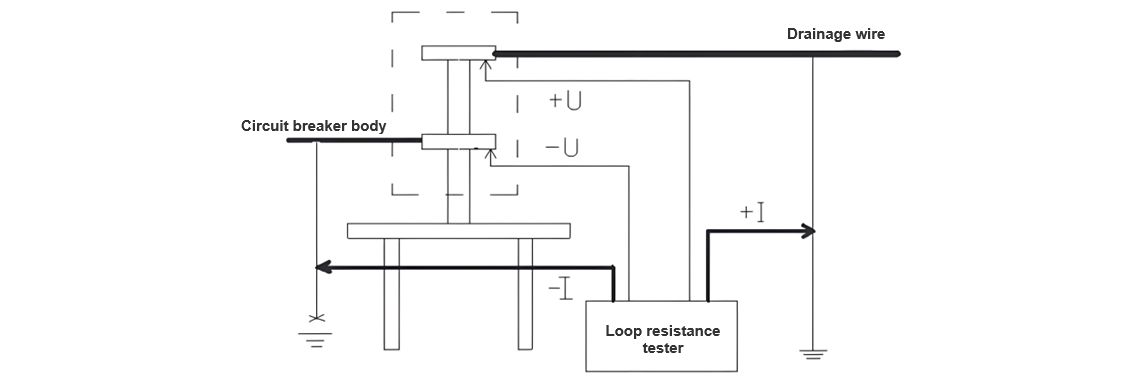
Ji bo testa rezezeyê li dereceya dûbarkirinê, metoda drop voltage hatîne afirandin. Prinsîpa metoda drop voltage ya ku di hemû derêzekan de di dema direct - current de derêz dike, voltaj drop di navbera rezeza serketina tayîna xwe de dibike. Di dema measurekirina derêza dike û voltaj drop di navbera testê de, rezeza serketina direct - current bi ser kanona Ohm: R = U/I bixebitandin. Şekla şemayê ya testa rezezeyê li dereceya dûbarkirinê (Şekil 1) weş:

Voltaj difference di navbera pointên potensiyaliyê de ye. Ger bimînin ku zemin zero - potensiyal ye, ewa fahmidina sadewa ku voltaj applied emforce e. Di vê cihan de, tuhama emforce di navbera du pointên testan de bikar bînin.
(2) Metoda Testê
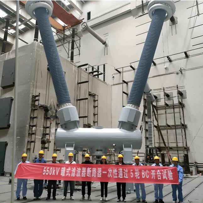
Şekila fizîkî ya testa rezezeyê li dereceya dûbarkirinê ya sulfur hexafluoride (SF₆) weş (Şekil 2):
Welatî dike, ji bo testên high - voltage li dereceyan dûbarkirinê, her du pêçên dereceya dûbarkirinê pêdivî ye ke reliable ground bikin. Ew teknîk e ku amana xebitiya we ya hêviya werbigire û di Safe Regulations de taybetandî kirin. Bi ser pergalîyên fundamental ên ku derêz bi navbera rota spesifik de dike, di testa rezezeyê de dereceya dûbarkirinê, wirazîn îngilizî yên grounding wire - în dike bikar bînin. Grounding wire cross - sectional area 25mm², ku dest pêk bixebitandin 200A, test requirements meet.
Di dema testê de, grounding point ya grounding wire ya her pêça dereceya dûbarkirinê diskerin, lê safe grounding ya work point ya pêça din jê bibe. Du pole ên current ên test instrument we li grounding wires ya her du pêça dereceya dûbarkirinê connect bikin. Bi vê rêzikar, current dike bi navbera grounding wires ya her du pêça dereceya dûbarkirinê, current loop test form bikin. Ji ber ku grounding point ya pêça dereceya dûbarkirinê di dema testê de diskerin, resistance ya grounding grid ji test loop exclude bikin, ji bo in ku test loop tu dereceya dûbarkirinê bibe û accuracy ya test ensure bikin.
Pêvek solution ya test voltage loop. Wires ên test voltage loop we li metal top rod ên insulating rod (metal top rod specially processed bibe pointed tip for good contact with terminal block of circuit breaker). Ji ber ku rezeza circuit breaker itself extremely small, even tiny transition resistance can cause significant errors. Di dema testê de, metal top rod ên insulating rod press against terminal block of circuit breaker (two insulating rods required, which are respectively pressed against the upper and lower terminal blocks of the circuit breaker). Since the wires of the test voltage loop are thin and light, they hardly affect the testers' operation of lifting the insulating rods for testing.
Reason why the current loop is formed by using the grounding wires on both sides of the circuit breaker is twofold. Firstly, the current wires are thick and heavy. Secondly, due to the large test current, good contact must be ensured; otherwise, the contact points will be eroded. If insulating rods were used to form the current loop, the increased weight of the insulating rods would make them difficult for testers to operate, and good contact could not be guaranteed.
The test is carried out as follows: First, we clamp the clips of the -I and +I leads onto the grounding wires on both sides of the circuit breaker. This can be completed by the staff standing on the ground, thus establishing the current loop. Then, the testers stand on the framework or mechanism box of the circuit breaker and press the metal top rods of the insulating rods connected to the voltage loop wires against the upper and lower terminal blocks of the circuit breaker respectively. It is crucial to ensure that -U corresponds to -I and +U corresponds to +I. In this way, the test loop is completed.
4 Analysis of Test Results
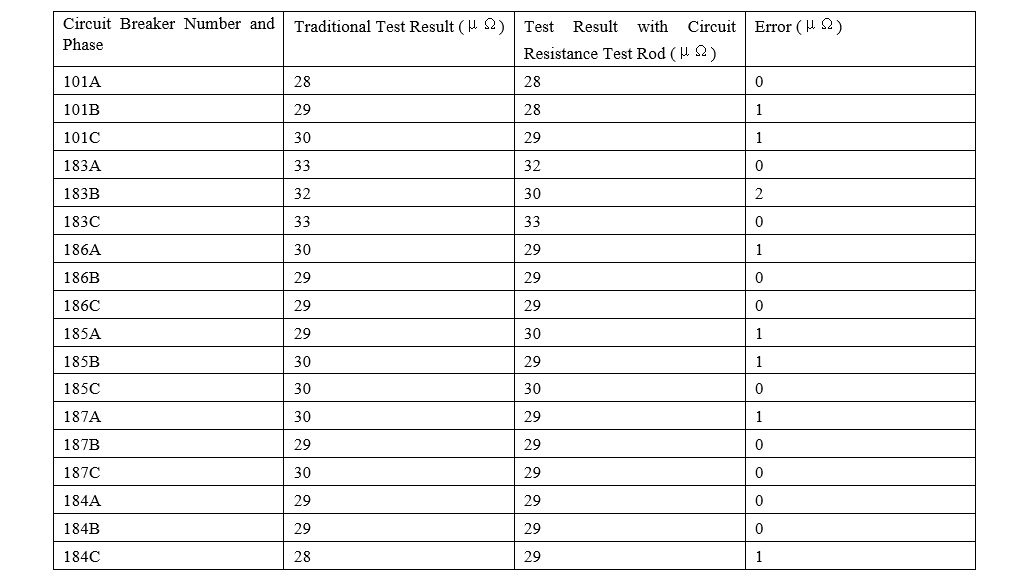
For testers, everything must be evidenced by data. Using specially prepared insulating rods for testing the circuit resistance of circuit breakers, we conducted circuit resistance tests on the 220kV and 110kV circuit breakers at the 220kV Haigeng Substation and 220kV Songming Substation under our jurisdiction.
220kV Haigeng Substation 110kV circuit breaker
220kV Songming Substation 220kV circuit breaker
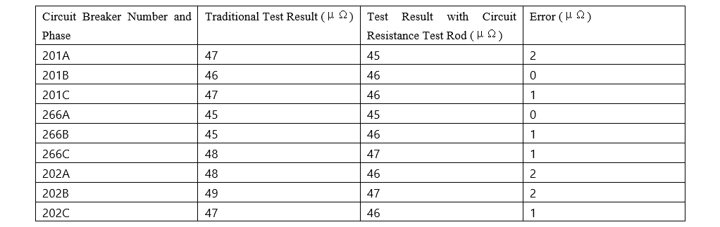
220kV Songming Substation 220kV circuit breaker
The test results obtained by the traditional method and the circuit resistance test rod are almost the same, with an error ranging from 1 to 2 μΩ. This error is acceptable, indicating that this method is feasible and accurate.
Comparison between the Circuit Resistance Test of Circuit Breakers Using the Circuit Resistance Test Rod and the Traditional Method
(1) Traditional Test Method
The traditional method requires workers to climb the circuit breaker or use an aerial work platform. Without climbing or using an aerial work platform, the test leads cannot be connected to the upper and lower terminal blocks of the circuit breaker.
(2) Test Using the Circuit Resistance Test Rod
5 Conclusion
Through the comparison between the conventional method and the method using the circuit resistance test rod for the circuit resistance test of circuit breakers, the superiority of using the circuit resistance test rod is fully demonstrated. Firstly, the operational risks during work are reduced, and safety is enhanced. Secondly, work efficiency is improved, and manpower and material resources are saved, which reduces costs for the safe operation of the power grid.