Ang mga circuit breaker adunay importante nga papel sa sistema sa kuryente. Sila mao ang mga pananglitan nga makakaputol, makakasira, ug makakatuban sa normal nga kuryente sa usa ka operasyon nga linya, ug makakatuban, makakasira, ug makakaputol sa naka-iskedyul nga abnormal nga kuryente ( sama sa short-circuit current) sa naka-iskedyul nga panahon. Maayo nga contact sa conductive circuit sa circuit breaker mahimong vital nga kondisyon aron masiguro ang maayong operasyon. Kon ang contact wala maayo, mahimo kini ang switch mag-overheat o moburn-out, resulta mao ang brownout sa power grid. Kung unsa ang sitwasyon sa contact sa conductive circuit sa circuit breaker mahimong masayri pinaagi sa circuit resistance test. Busa, ang pag-measure sa circuit resistance mahimong dili mapagpuyo nga bahin sa preventive tests. Hingpit, ang circuit resistance test sa 220kV sulfur hexafluoride (SF₆) circuit breaker gipangutana isip ehempiyo.
2. Pagsusi sa Kasamtangan nga Sitwasyon
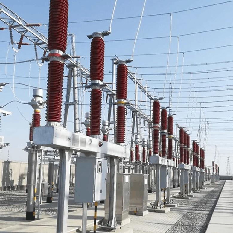
Sa kasamtangan nga operasyon sa power system, daghan sa 110kV ug 220kV systems nag-adopt og SF₆ circuit breakers. Sumala sa insulation design requirements sa circuit breaker mismo ug sa design requirements sa power system, ang taas sa 110kV circuit breaker karaniwan 2.5 metro, ug ang 220kV circuit breaker karaniwan 4 metro. Ania usab ang framework height nga humuya 2 metro. Ang total nga taas sa circuit breaker ania tali 4 hangtod 6 metro.
Arkon sa pag-conduct og circuit resistance test sa circuit breaker, kinahanglan ang ladders ug aerial work platforms. Padulong, para sa kasamtangan nga inverted-type SF₆ circuit breakers, wala na allowed ang pag-climb sa mga personal. Busa, kon ang circuit resistance test gibuhat pinaagi sa conventional nga test method, ang aerial work platform ra ang makagamit.
3. Summary sa mga Test Methods
(1) Test Principle
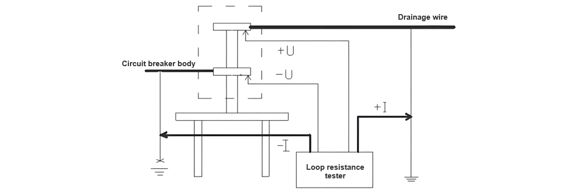
Para sa circuit resistance test sa circuit breaker, ang voltage-drop method ang gipangutana. Ang principle sa voltage-drop method mao ang kapag na-direct-current ang ipasa sa circuit under test, ang voltage drop mosunod sa contact resistance sa circuit. Pinaagi sa pag-measure sa current nga naga-pass sa circuit ug ang voltage drop sa circuit under test, ang contact direct-current resistance value makakalkula sumala sa Ohm's law: R = U/I. Ang schematic diagram sa circuit resistance test sa circuit breaker asa (Figure 1):

Ang voltage mao ang pagkain lain tali sa duha ka potential points. Kon ang ground ang zero-potential point, maka-unsa mi nga ang applied voltage mao ang electromotive force. Sa kasong niini, ang gi-need lang mao ang pag-apply og electromotive force tali sa duha ka test points gamit ang testing instrument.
(2) Test Method
Ang on-site physical connection diagram sa circuit resistance test sa sulfur hexafluoride (SF₆) circuit breaker asa (Figure 2):
Wala mailhan, sa pag-conduct og high-voltage tests sa circuit breakers, ang duha ka gilid sa circuit breaker kinahanglan na reliable nga grounded. Kini usa ka teknikal nga hakbang aron masiguro ang seguridad ug gihisgutan sa Safety Regulations. Sumala sa fundamental nga katangian nga ang current makuha ra sa specific nga ruta, sa panahon sa circuit resistance test sa circuit breaker, gigamit nato ang safety measure sa operation - ang grounding wire - isip current loop. Ang grounding wire adunay cross-sectional area nga 25mm², kini sufficient aron tubagon ang large current nga 200A, satisfying the test requirements.
Sa panahon sa test, giputli nato ang grounding point sa grounding wire sa usa ka gilid sa circuit breaker, samtang gipabalaka ang safe grounding sa working point sa uban nga gilid. Giconnect nato ang duha ka current poles sa test instrument sa grounding wires sa duha ka gilid sa circuit breaker. Sa sayon, ang current makapasa pinaagi sa grounding wires sa duha ka gilid, forming the current loop for the test. Tungod kay ang grounding point sa usa ka gilid sa circuit breaker giputli sa panahon sa test, ang resistance sa grounding grid wala na include sa test loop, ensuring that the test loop only includes the circuit breaker and guaranteeing the accuracy of the test.
Sunod mao ang solusyon sa test voltage loop. Giconnect nato ang wires sa test voltage loop sa metal top rod sa insulating rod (ang metal top rod adunay special nga proseso aron pointed tip para masiguro ang maayo nga contact sa terminal block sa circuit breaker). Tungod kay ang circuit resistance value sa circuit breaker mismo lisud, bisan small amount of transition resistance makadaghan sa errors. Sa panahon sa test, ang metal top rod sa insulating rod igpugos sa terminal block sa circuit breaker (duha ka insulating rods required, gipugos sa upper ug lower terminal blocks sa circuit breaker). Tungod kay ang wires sa test voltage loop thin ug light, wala na affect sa testers' operation sa lifting sa insulating rods for testing.
Ang rason kung unsaon ang current loop giporma pinaagi sa grounding wires sa duha ka gilid sa circuit breaker mao ang duha ka rason. Unsa, ang current wires thick ug heavy. Usa pa, tungod kay ang large test current, maayo nga contact sigurado; otherwise, ang contact points mogawas. Kon ang insulating rods gipangamit sa pag-form sa current loop, ang added weight sa insulating rods mahimong lisud sa testers' operation, ug maayo nga contact wala na sigurado.
Ang test gibuhat asa: Una, gipugos nato ang clips sa -I ug +I leads sa grounding wires sa duha ka gilid sa circuit breaker. Kini makacomplete sa staff standing sa ground, thus establishing the current loop. Pagkatapos, ang testers standing sa framework or mechanism box sa circuit breaker ug pugoson ang metal top rods sa insulating rods connected to the voltage loop wires sa upper ug lower terminal blocks sa circuit breaker respectively. Dili pwede ang -U correspond sa -I ug +U correspond sa +I. Sa sayon, ang test loop complete.
4 Pagsusi sa Resulta sa Test
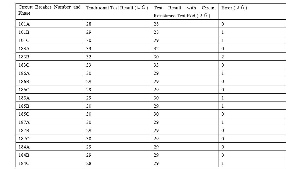
Para sa testers, tanang butang kinahanglan data. Gamit ang specially prepared insulating rods para sa testing sa circuit resistance sa circuit breakers, gibuhat nato ang circuit resistance tests sa 220kV ug 110kV circuit breakers sa 220kV Haigeng Substation ug 220kV Songming Substation sa atong jurisdiction.
220kV Haigeng Substation 110kV circuit breaker
220kV Songming Substation 220kV circuit breaker
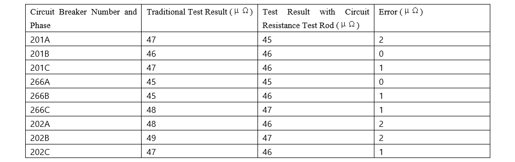
220kV Songming Substation 220kV circuit breaker
Ang resulta sa test nga gikinahanglan sa traditional method ug ang circuit resistance test rod halos parehas, ang error ranging from 1 to 2 μΩ. Kini acceptable, indicating that this method is feasible and accurate.
Comparison between the Circuit Resistance Test of Circuit Breakers Using the Circuit Resistance Test Rod and the Traditional Method
(1) Traditional Test Method
Ang traditional method kinahanglan ang workers mag-climb sa circuit breaker o magamit ang aerial work platform. Wala na climb o magamit ang aerial work platform, ang test leads wala makakonektar sa upper ug lower terminal blocks sa circuit breaker.
(2) Test Using the Circuit Resistance Test Rod
5 Conclusion
Sumala sa comparison tali sa conventional method ug ang method using the circuit resistance test rod sa circuit resistance test sa circuit breakers, ang superiority sa paggamit sa circuit resistance test rod fully demonstrated. Unsa, ang operational risks during work reduced, ug safety enhanced. Usa pa, work efficiency improved, ug manpower ug material resources saved, reducing costs for the safe operation of the power grid.