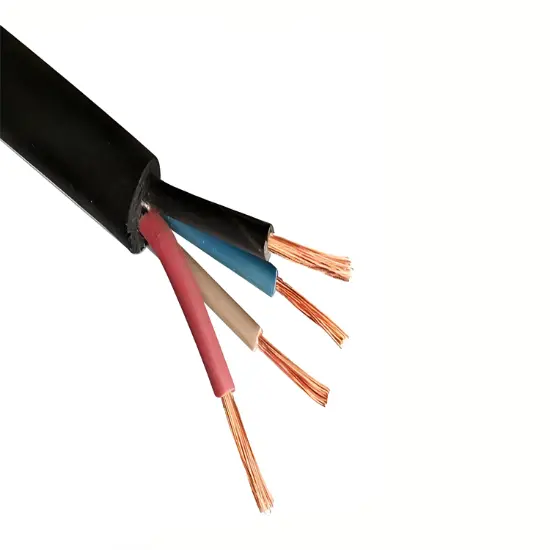
A single solid conductor
Peculiarity
A single solid conductor is the most basic type of conductor. It is made of a single metal material (such as copper or aluminum) and has the advantages of simple structure and high mechanical strength. Because of its solid structure, it has good conductivity at low frequencies and relatively uniform current distribution. For example, it may be used in some short-distance transmission lines that require high mechanical strength and low frequency (such as some indoor power wiring).
However, with the increase of transmission frequency, the skin effect will concentrate the current on the surface of the conductor, and the material inside the solid conductor can not be fully utilized, resulting in material waste, and it may limit its current carrying capacity due to heat dissipation problems during high current transmission.
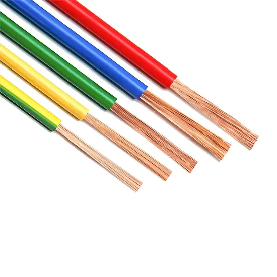
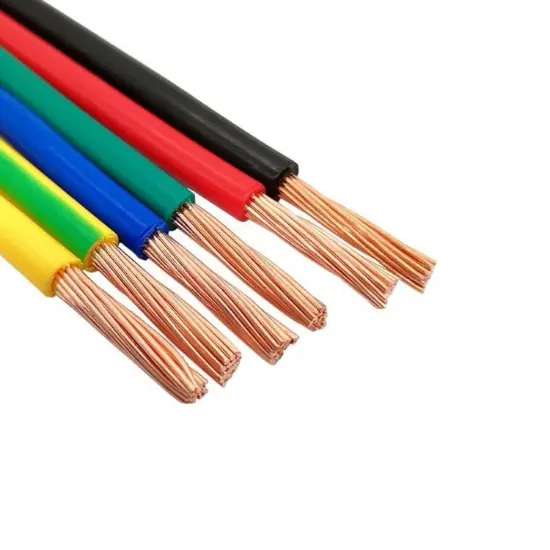
Stranded conductor
Peculiarity
A stranded conductor is composed of several smaller diameter wires twisted together. This structure increases the flexibility of the conductor, is easy to install and bend, and is suitable for transmission lines that need to be bent or moved frequently, such as the cable in the cable bridge or the power cord of some mobile devices.
The contact between the multiple wires of the stranded conductor increases the heat dissipation area to a certain extent and helps to improve the current carrying capacity. At the same time, since each small wire can be regarded as an independent current path, at high frequencies, the skin effect makes the current concentrate on the surface of each small wire, which is equivalent to increasing the total effective conductive area, which can better cope with high-frequency transmission than a single solid conductor. For example, in some high-frequency communication cables, stranded conductors are often used to improve signal transmission quality.
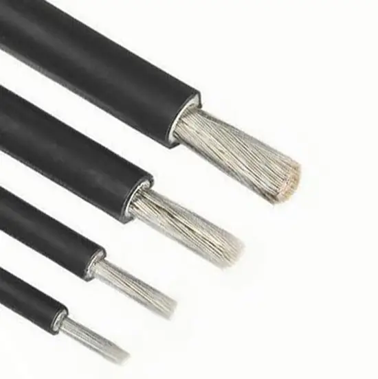
Hollow conductor
Peculiarity
The inside of the hollow conductor is hollow structure, and the current is mainly concentrated on the outer surface of the conductor. This structure effectively makes use of the skin effect, in high frequency transmission, because the current is concentrated on the surface, the hollow part does not have a substantial effect on the current transmission, but can reduce the weight of the conductor and save material.
Hollow conductors have certain applications in some transmission systems with strict weight requirements (such as transmission lines in the aerospace field) or long-span overhead transmission lines (to reduce the pressure of their own weight on the tower). However, the manufacturing process of hollow conductors is relatively complex, and the mechanical strength may be lower than that of solid conductors, and measures need to be taken in structural design to ensure adequate mechanical support.
Coaxial conductor
Peculiarity
A coaxial conductor consists of an inner conductor and an outer conductor separated by an insulating medium. The outer conductor is usually a hollow cylindrical conductor that surrounds the inner conductor in the middle. This structure has a good electromagnetic shielding characteristics, the inner conductor transmits the signal, the outer conductor is not only the return path of the signal, but also plays the role of shielding the external electromagnetic interference.
Coaxial conductors are widely used in high-frequency signal transmission (such as TV signal transmission, high-speed data transmission in computer networks, etc.). It can effectively transmit high-frequency signals, reduce signal attenuation and external interference, and ensure the quality of the signal. But the cost of coaxial cable is relatively high, and as the transmission distance increases, signal attenuation is still a problem to consider.