• Product
  • Suppliers
  • Manufacturers
  • Solutions
  • Free tools
  • Knowledges
  • Experts
  • Communities
Search


Typical sensor and control location in GIS according to IEC 61850

Encyclopedia
Encyclopedia
Field: Encyclopedia
0
China

Arrangement and Communication of GIS Control Elements

The positioning of control and communication components in Gas - Insulated Switchgear (GIS) can differ significantly based on the design choices of various manufacturers.

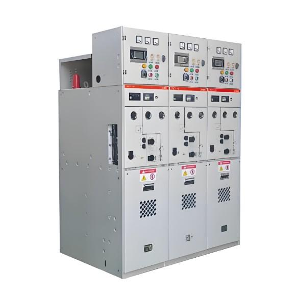
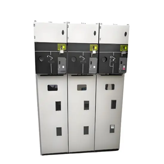
As illustrated in the accompanying figure, a typical configuration of GIS integrating switchgear controllers and communication elements features a circuit breaker controller (CBC) and a disconnector or earth switch controller (DCC) tailored for a three - phase pole setup. The CBC generally employs the logical node XCBR to manage circuit breakers, while the DCC typically utilizes the logical node XSWI for controlling disconnectors or earth switches. Additionally, GIS systems are equipped with sensors designed for monitoring and diagnosing partial discharges, enabling early detection of potential faults.

Functions such as bay control, bay interlocking, and local human - machine interfaces are often incorporated within the GIS control enclosure. These elements work in tandem to ensure seamless operation, enhanced safety, and user - friendly interaction with the switchgear.

Communication between the switchgear controllers and other substation components is established through serial communication links. Regarding the interface point A, it can be located on a section of the relevant communication device (referred to as the “com device”) or directly on the switchgear controllers (either CBC or DCC). For the internal connection type B, as specified in IEC62271 - 1 for switchgear controllers, strict compliance with IEC 61850 - 8 - 1 standards is required. This ensures interoperability and consistent communication protocols across different equipment, facilitating efficient data exchange and coordinated operation within the substation.

Give a tip and encourage the author!
Recommended
 Electrical Room Power-On Safety Operation Guide
Electrical Room Power-On Safety Operation Guide
Power Supply Procedure for Low-Voltage Electrical RoomsI. Pre-Power-On Preparations Clean the electrical room thoroughly; remove all debris from switchgear and transformers, and secure all covers. Inspect busbars and cable connections inside transformers and switchgear; ensure all screws are tightened. Live parts must maintain adequate safety clearance from cabinet enclosures and between phases. Test all safety equipment before energizing; use only calibrated measuring instruments. Prepare fire-
Echo
10/28/2025
Low-Voltage Distribution Cabinet Maintenance Steps and Safety Guide
Maintenance Procedure for Low-Voltage Power Distribution FacilitiesLow-voltage power distr ibution facilities refer to the infrastructure that delivers electrical power from a power supply room to end-user equipment, typically including distribution cabinets, cables, and wiring. To ensure the normal operation of these facilities and guarantee user safety and power supply quality, regular maintenance and servicing are essential. This article provides a detailed introduction to the maintenance pro
Edwiin
10/28/2025
Low-Voltage Electrical Work Safety Preparation and Operation Guide
Low-Voltage Electrician Safety Operating Procedures1. Safety Preparation Before performing any low-voltage electrical work, personnel must wear approved protective equipment, including insulating gloves, insulating boots, and insulating workwear. Carefully inspect all tools and equipment for proper operation. Report any damage or malfunction immediately for repair or replacement. Ensure adequate ventilation at the worksite. Avoid prolonged work in confined spaces to prevent fire hazards or poiso
Echo
10/28/2025
How to Handle Common Faults in RMU and Transformer Substations?
1. Ring Main Unit (RMU) and Transformer SubstationThe ring main unit (RMU) and transformer substation is a critical terminal in a distribution ring network system. The operational status of this terminal is directly affected by the performance of the distribution ring network system. Therefore, this section discusses the advantages, system composition, and key characteristics of the distribution ring network.1.1 Advantages of RMU and Transformer SubstationDue to technological limitations, radial
Felix Spark
10/28/2025
Related Products
Send inquiry
Download
Get the IEE Business Application
Use the IEE-Business app to find equipment, obtain solutions, connect with experts, and participate in industry collaboration anytime, anywhere—fully supporting the development of your power projects and business.