Rogowski Coil application in GIS

04/14/2025

Rogowski coils offer highly accurate secondary outputs without the risk of saturation since they do not incorporate an iron core. The air - core design ensures linear measurement, although it generates only a relatively small voltage (1V as opposed to 100V). This characteristic enables a compact equipment layout and allows for easy integration into Gas - Insulated Switchgear (GIS) with minimal space requirements due to the absence of an iron core. Additionally, Rogowski coils exhibit high immunity to noise and surge voltages because their coupling factor is significantly lower than that of coils with an iron core.
In a GIS enclosure, the primary conductor functions as the primary winding of the Rogowski coil. The secondary winding of the coil, which has an air core, is connected to an analog - to - digital converter within an Intelligent Electronic Device (IED). Subsequently, it is linked to the protection and control system via an optical bus. The primary conductor, operating at a high - voltage potential, carries the current and serves as the primary winding of the Rogowski coil.
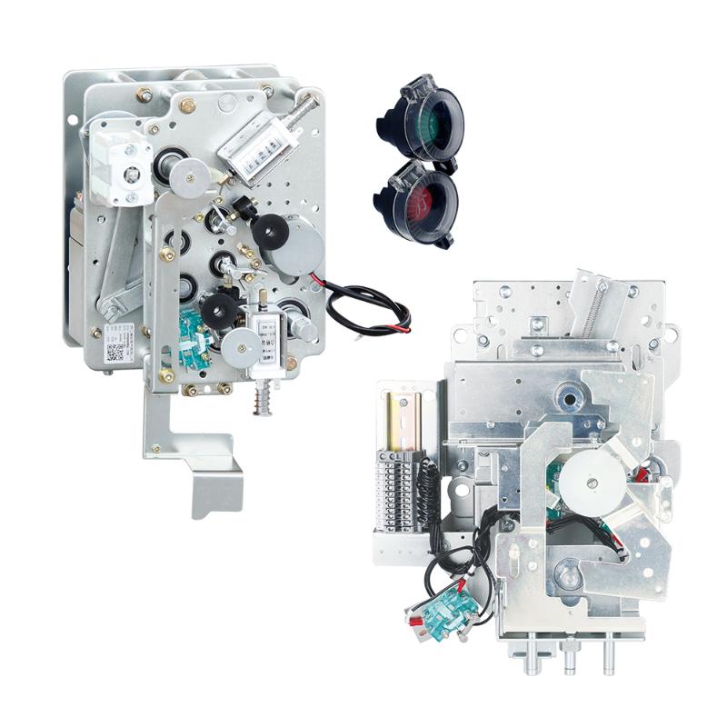
The secondary windings are at ground potential within the GIS enclosure. Their role is to transform the current in the primary conductor into an induced voltage in the secondary windings of the Rogowski coil. As shown in the photo, an electronic card then converts the measured value into a digital signal for connection to the control system.


Hello,I'm Wdwiin. A decade of hands-on experience in electrical engineering, specializing in high-voltage systems, smart grids, and renewable energy technologies. Passionate about technical exchange and knowledge sharing, committed to interpreting industry trends with professional insights to empower peers. Connection creates value—let’s explore the boundless possibilities of the electrical world together!

What is the difference between a dielectric and an insulator?
Dielectrics and insulators are distinguished primarily by their applications. One of the main differences is that a dielectric can store electrical energy by becoming polarized in an electric field, whereas an insulator resists the flow of electrons to prevent current conduction. Other key differences between them are outlined in the comparison chart below.Definition of DielectricA dielectric material is a type of insulator that contains few or no free electrons. When subjected to an electric fi
08/30/2025
What losses occur during operation of the transformer? How to reduce losses?
Transformers experience various types of losses during operation, primarily categorized into two main types: copper losses and iron losses.Copper LossesCopper losses, also known as I²R losses, are caused by the electrical resistance of the transformer windings—typically made of copper. As current flows through the windings, energy is dissipated in the form of heat. These losses are proportional to the square of the load current (I²R), meaning they increase significantly with high
Rockwell
08/29/2025
Cable Fault Detection, Testing, Location and Repair
I. Methods for Cable Testing and Inspection:Insulation Resistance Test: Use an insulation resistance tester to measure the insulation resistance value of the cable. A high insulation resistance value indicates good insulation, while a low value may suggest insulation problems requiring further investigation.Voltage Withstand Test: Apply a high-voltage test using a high-voltage tester to verify whether the cable can withstand high voltage under its rated operating conditions. Under normal circums
08/29/2025
Cable Quality Inspection and Cable Detection & Testing
Power cable quality inspection and cable testing are conducted to ensure that the cable's quality and performance meet specified requirements, thereby guaranteeing the safe and stable operation of power systems. Below are some common contents of power cable quality inspection and cable testing:Visual Inspection: Check the cable surface for physical defects such as damage, deformation, or scratches to ensure the cable's exterior is intact.Dimensional Measurement: Measure dimensional parameters su
08/29/2025
Inquiry
Download
IEE-Business is dedicated to serving the personnel in the global power industry.
Join IEE-Business, not only can you discover power equipment and power knowledge, but also canhnd like - minded friends!