Circuituum Interruptorum Classificatio
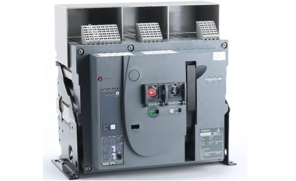
(1) Circuitum Interruptor Aeris (ACB)
Circuitus interruptor aeris, etiam notus ut circuitus interruptor formae malleabilis vel universalis, omnes componentes intra framea metallica insulata continet. Saepe est typus apertus, permittens installationem variarum accessoriarum, et facilitat substitutionem contactuum et partium. Communiter utitur ut commutator principale alimenti. Unitates trip overcurrent includunt typos electromagneticos, electronicos, et intelligentes. Interruptor praebet protectionem quattuor stadii: longi temporis mora, brevi temporis mora, instantanea, et terra fault protection. Unamquamque protectionem adiustare potest in gradu secundum magnitudinem frameae.
Interruptores aeris apti sunt pro AC 50Hz, tensionibus nominatis 380V vel 660V, et currentibus nominatis ab 200A ad 6300A in rete distributionis. Principale usus est distribuere energiam electricam et protegere circuitus et apparatus potentiae ab overloads, undervoltage, short circuits, single-phase grounding, et alii defectus. Hi interruptores praebent plures functiones protectionis intelligentis et permittere protectionem selectivam. Sub conditionibus normalibus, possunt adhiberi ad infrequentes commutationes circuituum. ACBs cum ratingibus usque ad 1250A possunt adhiberi in rete AC 50Hz, 380V ad protegendum motrices contra overloads et short circuits.

Interruptores aeris communiter utuntur ut commutatores principales in latere 400V transformatorum, bus tie switches, high-capacity feeder switches, et magnis commutatoribus controlis motorum.
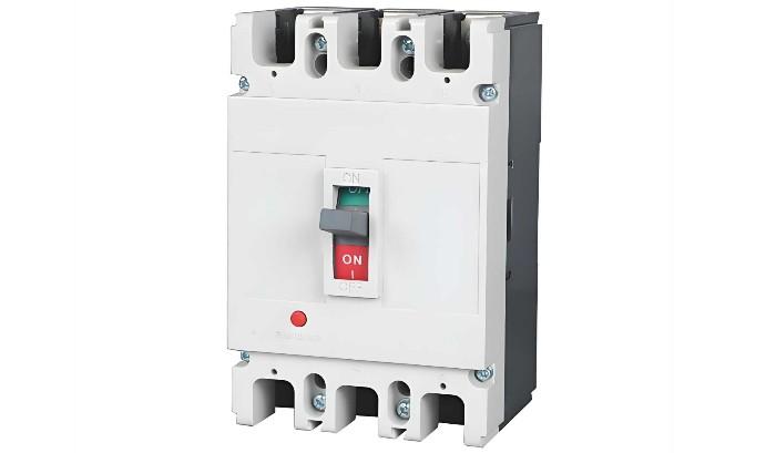
(2) Molded Case Circuit Breaker (MCCB)
Etiam notus ut circuitus interruptor insertus, MCCB terminales, contactus, arc extinguishing chambers, unitates trip, et mechanismos operationis intra enclosure plasticam continet. Contactus auxiliares, undervoltage trip units, et shunt trip units saepe sunt modulares. Structura compacta, et maintenance non consideratur. Aptus est pro protectione branch circuit. MCCBs communiter includunt thermal-magnetic trip units, maioribus modellis solid-state trip sensors equipari possunt.
Overcurrent trip units pro MCCBs disponuntur in typos electromagneticos et electronicos. Electromagnetic MCCBs sunt non-selectivi et praebent solum longi temporis moram et protectionem instantaneam. Electronic MCCBs offerunt quattuor functiones protectionis: longi temporis mora, brevi temporis mora, instantanea, et terra fault protection. Quaedam novissime introducta electronic MCCBs featurent zone-selective interlocking.

Molded case circuit breakers generaliter utuntur pro controlu et protectione circuituum feeder, commutatoribus principalibus in latere basso-voltantis parvorum transformatorum distributionis, controlu terminali distributionis potentiae, et ut commutatoribus potentiae variorum machinarum productionis.
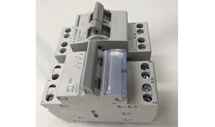
(3) Miniature Circuit Breaker (MCB)
Miniature circuit breaker est maximus usus terminalis dispositivus protectionis in systemibus distributionis electrica edificiorum. Utitur ad protectionem contra short circuits, overloads, et overvoltage in circuitibus uniphasicis et triphasics usque ad 125A, et venit in configurationibus unipolare (1P), bipolare (2P), tripolare (3P), et quadripolare (4P).
MCB constat ex mechanismo operationis, contactibus, dispositivis protectionis (various trip units), et systemate arc extinguishing. Contactus principales manu aut electriciter clauduntur. Post clausuram, liber-tripping mechanismus contactus in positione clausa concludit. Coil overcurrent trip unit et elementum calefactionis thermal trip unit series cum circuitu principali iunguntur, dum coil undervoltage trip unit parallel cum alimentatione iungitur.

In design electrica edificiorum civilium, miniature circuit breakers primarie utuntur ad protectionem et operationem sicut overload, short circuit, overcurrent, loss of voltage, undervoltage, grounding, leakage, automatic transfer of dual power sources, et infrequent motor starting.
Characteristica Parametera Basica Interruptorum Circuituum
(1) Tensio Nominata Operationis (Ue)
Tensio nominata operationis est tensio nominalis interruptoris circuitus, sub qua interruptor potest continue operari sub condicionibus normalibus et performance specificatis.
In China, pro nivelibus tensionis usque ad 220kV, maximum tensio operationis est 1.15 times system rated voltage; pro 330kV et super, maximum tensio operationis est 1.1 times rated voltage. Interruptor debet insulationem retinere et capax esse claudi et interrupti sub systematis maxima tensio operationis.
(2) Currentus Nominatus (In)
Currentus nominatus est currentus quem unitas trip portare potest continue sub temperatura ambienti infra 40°C. Pro interruptoribus cum adjustable trip units, referetur ad maximum currentum quem unitas trip portare potest continue.
Quando adhibetur in temperaturis ambientibus supra 40°C sed non excedentibus 60°C, interruptor posset operari sub reducenda onera pro servitio longo tempore.
(3) Overload Trip Current Setting (Ir)
Cum currentus excedit setting Ir unitatis trip, interruptor circuitus post moram temporis trip facit. Etiam repraesentat maximum currentum quem interruptor portare potest sine trip. Hoc valor debet esse maior quam maximum currentus oneris Ib sed minor quam maximum currentus permittibilis Iz circuitus.
Pro thermal-magnetic trip units, Ir est solito adiustabilis intra 0.7–1.0In. Pro electronic trip units, adiustamentum range est solito latius, solito 0.4–1.0In. Pro interruptoribus cum non-adjustable overcurrent trip units, Ir = In.
(4) Short-Circuit Trip Current Setting (Im)
Unitas trip short-circuit (instantaneous vel short-time delay) facit interruptorem circuitus trip celeriter quando alta currentus defectus occurrunt. Eius threshold trip est Im.
(5) Rated Short-Time Withstand Current (Icw)
Hoc est valor currentus permitti per conductorem pro tempore specificato sine damnum propter overheating.
(6) Breaking Capacity
Breaking capacity interruptoris circuitus refert ad eius capacitas securiter interrupti currentus defectus, quod non necessario relatum est ad eius currentum nominatum. Communes ratings includunt 36kA et 50kA. Generaliter dividitur in ultimate short-circuit breaking capacity (Icu) et service short-circuit breaking capacity (Ics).
General Principles for Circuit Breaker Selection
Primum, select type and number of poles based on application; then select the rated current based on maximum operating current; finally, choose the type of trip unit and accessories. Specific requirements are as follows:
Rated operating voltage of the circuit breaker ≥ line rated voltage.
Rated short-circuit making/breaking capacity of the circuit breaker ≥ calculated load current of the line.
Rated short-circuit making/breaking capacity of the circuit breaker ≥ maximum possible short-circuit current in the line (usually calculated as RMS value).
Single-phase-to-ground short-circuit current at the end of the line ≥ 1.25 times the instantaneous (or short-time delay) trip setting of the circuit breaker.
Rated voltage of the undervoltage trip unit = line rated voltage.
Rated voltage of the shunt trip unit = control power supply voltage.
Rated operating voltage of the electric operating mechanism = control power supply voltage.
When used in lighting circuits, the instantaneous trip setting of the electromagnetic trip unit is generally 6 times the load current.
When using a circuit breaker for short-circuit protection of a single motor, the instantaneous trip setting is 1.35 times the motor starting current (for DW series) or 1.7 times (for DZ series).
When using a circuit breaker for short-circuit protection of multiple motors, the instantaneous trip setting is 1.3 times the starting current of the largest motor plus the operating currents of the remaining motors.
When using a circuit breaker as the main switch on the low-voltage side of a distribution transformer, its breaking capacity should exceed the short-circuit current on the low-voltage side of the transformer. The trip unit’s rated current should not be less than the transformer’s rated current. The short-circuit protection setting is generally 6–10 times the transformer’s rated current; the overload protection setting equals the transformer’s rated current.
After preliminarily selecting the circuit breaker type and rating, coordination with upstream and downstream protective devices is required to avoid cascading tripping and minimize accident scope.
Selectivity of Circuit Breakers
In distribution systems, circuit breakers are classified as selective or non-selective based on protection performance. Selective low-voltage circuit breakers have either two-stage or three-stage protection. Instantaneous and short-time delay characteristics are used for short-circuit protection, while long-time delay characteristics are used for overload protection. Non-selective breakers are typically instantaneous, used only for short-circuit protection, or long-time delay, used only for overload protection.
In distribution systems, if the upstream breaker is selective and the downstream breaker is non-selective or selective, selectivity is achieved by utilizing the time delay of the short-time delay trip unit or differences in time delay settings. When the upstream breaker operates with time delay, consider the following:
Regardless of whether the downstream breaker is selective or non-selective, the instantaneous overcurrent trip setting of the upstream breaker should generally be no less than 1.1 times the maximum three-phase short-circuit current at the downstream breaker’s output.
If the downstream breaker is non-selective, to prevent the upstream short-time delay overcurrent trip unit from operating first due to insufficient sensitivity of the downstream instantaneous trip unit during a short circuit, the short-time delay overcurrent trip setting of the upstream breaker should generally be no less than 1.2 times that of the downstream breaker’s instantaneous trip unit.
If the downstream breaker is also selective, to ensure selectivity, the short-time delay operating time of the upstream breaker should be at least 0.1 seconds longer than that of the downstream breaker.
Generally, to ensure selective operation between upstream and downstream low-voltage circuit breakers, the upstream breaker should preferably have a short-time delay overcurrent trip unit, and its operating current should be at least one level higher than that of the downstream trip unit. At minimum, the upstream operating current Iop.1 should be no less than 1.2 times the downstream operating current Iop.2, i.e., Iop.1 ≥ 1.2Iop.2.
Cascading Protection of Circuit Breakers
In distribution system design, coordination between upstream and downstream circuit breakers must achieve "selectivity, speed, and sensitivity." Selectivity relates to coordination between breakers, while speed and sensitivity are associated with the characteristics of the protective device and the operating mode of the circuit.
Proper coordination between upstream and downstream breakers enables selective isolation of the faulty circuit, ensuring other non-faulty circuits continue normal operation. Poor coordination affects system reliability.
Cascading protection is a practical application of the current-limiting characteristics of circuit breakers. Its main principle is to utilize the current-limiting effect of the upstream breaker (QF1), which allows selection of a downstream breaker (QF2) with lower breaking capacity, thus reducing cost. The current-limiting upstream breaker QF1 can interrupt the maximum prospective short-circuit current at its installation point. Since the upstream and downstream breakers are connected in series, when a short circuit occurs at the output of the downstream breaker QF2, the actual short-circuit current is significantly reduced by the current-limiting effect of QF1, far below the prospective short-circuit current at that point. Thus, the breaking capacity of QF2 is effectively enhanced by QF1, exceeding its rated breaking capacity.
Cascading protection has certain conditions: for example, adjacent circuits should not have critical loads (since tripping of QF1 would also de-energize QF3’s circuit), and the instantaneous settings of QF1 and QF2 must be properly matched. Cascading data can only be determined experimentally, and coordination between upstream and downstream breakers must be provided by the manufacturer.
Sensitivity of Circuit Breakers
To ensure reliable operation of the instantaneous or short-time delay overcurrent trip unit under minimum system operating conditions and during the mildest short-circuit fault within its protection range, the sensitivity of the circuit breaker must meet the requirements of the "Low-Voltage Electrical Distribution Design Code" (GB50054-95), which specifies a sensitivity of no less than 1.3, i.e., Sp = Ik.min / Iop ≥ 1.3. Here, Iop is the operating current of the instantaneous or short-time delay overcurrent trip unit, Ik.min is the single-phase or two-phase short-circuit current at the end of the protected line under minimum system operating conditions, and Sp is the sensitivity of the circuit breaker.
When selecting a circuit breaker, its sensitivity should also be verified. For selective breakers with both short-time delay and instantaneous overcurrent trip units, only the sensitivity of the short-time delay trip unit needs to be checked; the sensitivity of the instantaneous trip unit does not require verification.
Selection and Setting of Circuit Breaker Trip Units
(1) Setting of Instantaneous Overcurrent Trip Unit Operating Current
Some electrical equipment protected by the circuit breaker has high peak currents during startup, several times the rated current, causing the breaker to experience high peak currents briefly. The operating current Iop(o) of the instantaneous overcurrent trip unit must exceed the circuit’s peak current Ipk, i.e., Iop(o) ≥ Krel·Ipk, where Krel is the reliability factor. When selecting a circuit breaker, ensure its instantaneous overcurrent trip setting exceeds the peak current to prevent nuisance tripping.
(2) Setting of Short-Time Delay Overcurrent Trip Unit Operating Current and Time
The operating current Iop(s) of the short-time delay overcurrent trip unit should also exceed the circuit’s peak current Ipk, i.e., Iop(s) ≥ Krel·Ipk, where Krel is the reliability factor. Short-time delay trip times are generally 0.2s, 0.4s, or 0.6s, determined based on selectivity with upstream and downstream protection devices, ensuring the upstream device operates later than the downstream by one time step.
(3) Setting of Long-Time Delay Overcurrent Trip Unit Operating Current and Time
The long-time delay overcurrent trip unit is primarily used for overload protection. Its operating current Iop(l) only needs to exceed the circuit’s maximum load current (calculated current I30), i.e., Iop(l) ≥ Krel·I30, where Krel is the reliability factor. The operating time should exceed the duration of allowable short-term overloads to prevent nuisance tripping.
(4) Coordination Requirements Between Overcurrent Trip Unit Operating Current and Protected Circuit
To prevent insulation damage or fire due to overloads or short circuits without the circuit breaker tripping, the overcurrent trip unit’s operating current Iop must satisfy the condition: Iop ≤ Kol·Ial. Here, Ial is the allowable current-carrying capacity of the insulated cable; Kol is the allowable short-term overload factor—typically 4.5 for instantaneous and short-time delay trip units, 1.1 for long-time delay trip units used for short-circuit protection, and 1.0 when used only for overload protection. If this coordination requirement is not met, the trip unit setting should be adjusted, or the conductor or cable cross-section should be increased appropriately.


