Classification of Circuit Breakers
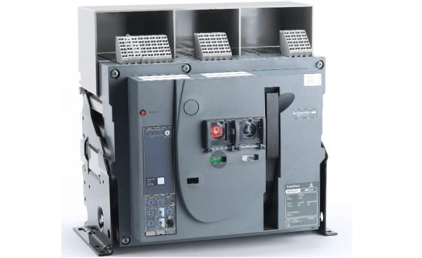
(1) Air Circuit Breaker (ACB)
An air circuit breaker, also known as a molded frame or universal circuit breaker, houses all components within an insulated metal frame. It is typically open-type, allowing installation of various accessories, and facilitates easy replacement of contacts and parts. It is commonly used as the main power supply switch. Overcurrent trip units include electromagnetic, electronic, and intelligent types. The breaker provides four-stage protection: long-time delay, short-time delay, instantaneous, and ground fault protection. Each protection setting can be adjusted within a range based on the frame size.
Air circuit breakers are suitable for AC 50Hz, rated voltages of 380V or 660V, and rated currents from 200A to 6300A in distribution networks. They are primarily used to distribute electrical energy and protect circuits and power equipment from overloads, undervoltage, short circuits, single-phase grounding, and other faults. These breakers offer multiple intelligent protection functions and enable selective protection. Under normal conditions, they can be used for infrequent switching of circuits. ACBs with ratings up to 1250A can be used in AC 50Hz, 380V networks to protect motors against overload and short circuits.

Air circuit breakers are also commonly used as main switches on the 400V side of transformers, bus tie switches, high-capacity feeder switches, and large motor control switches.
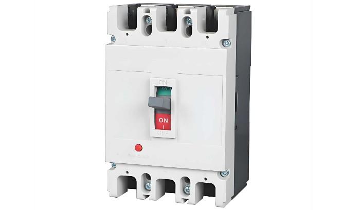
(2) Molded Case Circuit Breaker (MCCB)
Also known as a plug-in circuit breaker, the molded case circuit breaker houses terminals, contacts, arc extinguishing chambers, trip units, and operating mechanisms within a plastic enclosure. Auxiliary contacts, undervoltage trip units, and shunt trip units are often modular. The structure is compact, and maintenance is generally not considered. It is suitable for branch circuit protection. Molded case breakers typically include thermal-magnetic trip units, while larger models may be equipped with solid-state trip sensors.
Overcurrent trip units for MCCBs are available in electromagnetic and electronic types. Typically, electromagnetic MCCBs are non-selective and provide only long-time delay and instantaneous protection. Electronic MCCBs offer four protection functions: long-time delay, short-time delay, instantaneous, and ground fault protection. Some newly introduced electronic MCCBs also feature zone-selective interlocking.

Molded case circuit breakers are generally used for feeder circuit control and protection, main switches on the low-voltage side of small distribution transformers, terminal power distribution control, and as power switches for various production machinery.
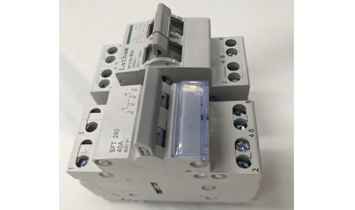
(3) Miniature Circuit Breaker (MCB)
The miniature circuit breaker is the most widely used terminal protection device in building electrical terminal distribution systems. It is used for protection against short circuits, overloads, and overvoltage in single-phase and three-phase circuits up to 125A, and comes in single-pole (1P), double-pole (2P), triple-pole (3P), and four-pole (4P) configurations.
An MCB consists of an operating mechanism, contacts, protective devices (various trip units), and an arc extinguishing system. The main contacts are closed manually or electrically. After closing, a free-tripping mechanism locks the contacts in the closed position. The coil of the overcurrent trip unit and the heating element of the thermal trip unit are connected in series with the main circuit, while the coil of the undervoltage trip unit is connected in parallel with the power supply.

In civil building electrical design, miniature circuit breakers are primarily used for protection and operation purposes such as overload, short circuit, overcurrent, loss of voltage, undervoltage, grounding, leakage, automatic transfer of dual power sources, and infrequent motor starting.
Basic Characteristic Parameters of Circuit Breakers
(1) Rated Operating Voltage (Ue)
The rated operating voltage is the nominal voltage of the circuit breaker, under which the breaker can operate continuously under specified normal service and performance conditions.
In China, for voltage levels up to 220kV, the maximum operating voltage is 1.15 times the system rated voltage; for 330kV and above, the maximum operating voltage is 1.1 times the rated voltage. The circuit breaker must maintain insulation and be capable of closing and interrupting under the system's maximum operating voltage.
(2) Rated Current (In)
The rated current is the current that the trip unit can carry continuously at an ambient temperature below 40°C. For breakers with adjustable trip units, it refers to the maximum current the trip unit can carry continuously.
When used in ambient temperatures above 40°C but not exceeding 60°C, the breaker may operate at a reduced load for long-term service.
(3) Overload Trip Current Setting (Ir)
When current exceeds the trip unit's setting Ir, the circuit breaker trips after a time delay. It also represents the maximum current the breaker can carry without tripping. This value must be greater than the maximum load current Ib but less than the maximum allowable current Iz of the circuit.
For thermal-magnetic trip units, Ir is typically adjustable within 0.7–1.0In. For electronic trip units, the adjustment range is usually wider, typically 0.4–1.0In. For breakers with non-adjustable overcurrent trip units, Ir = In.
(4) Short-Circuit Trip Current Setting (Im)
The short-circuit trip unit (instantaneous or short-time delay) causes the circuit breaker to trip quickly when high fault currents occur. Its trip threshold is Im.
(5) Rated Short-Time Withstand Current (Icw)
This is the current value allowed to pass through the conductor for a specified duration without causing damage due to overheating.
(6) Breaking Capacity
The breaking capacity of a circuit breaker refers to its ability to safely interrupt fault currents, which is not necessarily related to its rated current. Common ratings include 36kA and 50kA. It is generally divided into ultimate short-circuit breaking capacity (Icu) and service short-circuit breaking capacity (Ics).
General Principles for Circuit Breaker Selection
First, select the type and number of poles based on application; then select the rated current based on maximum operating current; finally, choose the type of trip unit and accessories. Specific requirements are as follows:
The circuit breaker’s rated operating voltage ≥ line rated voltage.
The circuit breaker’s rated short-circuit making/breaking capacity ≥ calculated load current of the line.
The circuit breaker’s rated short-circuit making/breaking capacity ≥ maximum possible short-circuit current in the line (usually calculated as RMS value).
Single-phase-to-ground short-circuit current at the end of the line ≥ 1.25 times the instantaneous (or short-time delay) trip setting of the circuit breaker.
The rated voltage of the undervoltage trip unit = line rated voltage.
The rated voltage of the shunt trip unit = control power supply voltage.
The rated operating voltage of the electric operating mechanism = control power supply voltage.
When used in lighting circuits, the instantaneous trip setting of the electromagnetic trip unit is generally 6 times the load current.
When using a circuit breaker for short-circuit protection of a single motor, the instantaneous trip setting is 1.35 times the motor starting current (for DW series) or 1.7 times (for DZ series).
When using a circuit breaker for short-circuit protection of multiple motors, the instantaneous trip setting is 1.3 times the starting current of the largest motor plus the operating currents of the remaining motors.
When using a circuit breaker as the main switch on the low-voltage side of a distribution transformer, its breaking capacity should exceed the short-circuit current on the low-voltage side of the transformer. The trip unit’s rated current should not be less than the transformer’s rated current. The short-circuit protection setting is generally 6–10 times the transformer’s rated current; the overload protection setting equals the transformer’s rated current.
After preliminarily selecting the circuit breaker type and rating, coordination with upstream and downstream protective devices is required to avoid cascading tripping and minimize accident scope.
Selectivity of Circuit Breakers
In distribution systems, circuit breakers are classified as selective or non-selective based on protection performance. Selective low-voltage circuit breakers have either two-stage or three-stage protection. Instantaneous and short-time delay characteristics are used for short-circuit protection, while long-time delay characteristics are used for overload protection. Non-selective breakers are typically instantaneous, used only for short-circuit protection, or long-time delay, used only for overload protection.
In distribution systems, if the upstream breaker is selective and the downstream breaker is non-selective or selective, selectivity is achieved by utilizing the time delay of the short-time delay trip unit or differences in time delay settings. When the upstream breaker operates with time delay, consider the following:
Regardless of whether the downstream breaker is selective or non-selective, the instantaneous overcurrent trip setting of the upstream breaker should generally be no less than 1.1 times the maximum three-phase short-circuit current at the downstream breaker’s output.
If the downstream breaker is non-selective, to prevent the upstream short-time delay overcurrent trip unit from operating first due to insufficient sensitivity of the downstream instantaneous trip unit during a short circuit, the short-time delay overcurrent trip setting of the upstream breaker should generally be no less than 1.2 times that of the downstream breaker’s instantaneous trip unit.
If the downstream breaker is also selective, to ensure selectivity, the short-time delay operating time of the upstream breaker should be at least 0.1 seconds longer than that of the downstream breaker.
Generally, to ensure selective operation between upstream and downstream low-voltage circuit breakers, the upstream breaker should preferably have a short-time delay overcurrent trip unit, and its operating current should be at least one level higher than that of the downstream trip unit. At minimum, the upstream operating current Iop.1 should be no less than 1.2 times the downstream operating current Iop.2, i.e., Iop.1 ≥ 1.2Iop.2.
Cascading Protection of Circuit Breakers
In distribution system design, coordination between upstream and downstream circuit breakers must achieve "selectivity, speed, and sensitivity." Selectivity relates to coordination between breakers, while speed and sensitivity are associated with the characteristics of the protective device and the operating mode of the circuit.
Proper coordination between upstream and downstream breakers enables selective isolation of the faulty circuit, ensuring other non-faulty circuits continue normal operation. Poor coordination affects system reliability.
Cascading protection is a practical application of the current-limiting characteristics of circuit breakers. Its main principle is to utilize the current-limiting effect of the upstream breaker (QF1), which allows selection of a downstream breaker (QF2) with lower breaking capacity, thus reducing cost. The current-limiting upstream breaker QF1 can interrupt the maximum prospective short-circuit current at its installation point. Since the upstream and downstream breakers are connected in series, when a short circuit occurs at the output of the downstream breaker QF2, the actual short-circuit current is significantly reduced by the current-limiting effect of QF1, far below the prospective short-circuit current at that point. Thus, the breaking capacity of QF2 is effectively enhanced by QF1, exceeding its rated breaking capacity.
Cascading protection has certain conditions: for example, adjacent circuits should not have critical loads (since tripping of QF1 would also de-energize QF3’s circuit), and the instantaneous settings of QF1 and QF2 must be properly matched. Cascading data can only be determined experimentally, and coordination between upstream and downstream breakers must be provided by the manufacturer.
Sensitivity of Circuit Breakers
To ensure reliable operation of the instantaneous or short-time delay overcurrent trip unit under minimum system operating conditions and during the mildest short-circuit fault within its protection range, the sensitivity of the circuit breaker must meet the requirements of the "Low-Voltage Electrical Distribution Design Code" (GB50054-95), which specifies a sensitivity of no less than 1.3, i.e., Sp = Ik.min / Iop ≥ 1.3. Here, Iop is the operating current of the instantaneous or short-time delay overcurrent trip unit, Ik.min is the single-phase or two-phase short-circuit current at the end of the protected line under minimum system operating conditions, and Sp is the sensitivity of the circuit breaker.
When selecting a circuit breaker, its sensitivity should also be verified. For selective breakers with both short-time delay and instantaneous overcurrent trip units, only the sensitivity of the short-time delay trip unit needs to be checked; the sensitivity of the instantaneous trip unit does not require verification.
Selection and Setting of Circuit Breaker Trip Units
(1) Setting of Instantaneous Overcurrent Trip Unit Operating Current
Some electrical equipment protected by the circuit breaker has high peak currents during startup, several times the rated current, causing the breaker to experience high peak currents briefly. The operating current Iop(o) of the instantaneous overcurrent trip unit must exceed the circuit’s peak current Ipk, i.e., Iop(o) ≥ Krel·Ipk, where Krel is the reliability factor. When selecting a circuit breaker, ensure its instantaneous overcurrent trip setting exceeds the peak current to prevent nuisance tripping.
(2) Setting of Short-Time Delay Overcurrent Trip Unit Operating Current and Time
The operating current Iop(s) of the short-time delay overcurrent trip unit should also exceed the circuit’s peak current Ipk, i.e., Iop(s) ≥ Krel·Ipk, where Krel is the reliability factor. Short-time delay trip times are generally 0.2s, 0.4s, or 0.6s, determined based on selectivity with upstream and downstream protection devices, ensuring the upstream device operates later than the downstream by one time step.
(3) Setting of Long-Time Delay Overcurrent Trip Unit Operating Current and Time
The long-time delay overcurrent trip unit is primarily used for overload protection. Its operating current Iop(l) only needs to exceed the circuit’s maximum load current (calculated current I30), i.e., Iop(l) ≥ Krel·I30, where Krel is the reliability factor. The operating time should exceed the duration of allowable short-term overloads to prevent nuisance tripping.
(4) Coordination Requirements Between Overcurrent Trip Unit Operating Current and Protected Circuit
To prevent insulation damage or fire due to overloads or short circuits without the circuit breaker tripping, the overcurrent trip unit’s operating current Iop must satisfy the condition: Iop ≤ Kol·Ial. Here, Ial is the allowable current-carrying capacity of the insulated cable; Kol is the allowable short-term overload factor—typically 4.5 for instantaneous and short-time delay trip units, 1.1 for long-time delay trip units used for short-circuit protection, and 1.0 when used only for overload protection. If this coordination requirement is not met, the trip unit setting should be adjusted, or the conductor or cable cross-section should be increased appropriately.


