Sirket Kəsənlərinin Sınıflandırılması
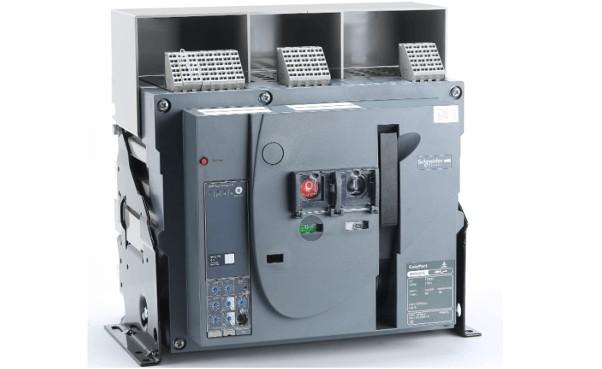
(1) Hava Sirket Kəsəni (ACB)
Hava sirket kəsəni, ya da döyüşülmüş qab və ya universal sirket kəsəni, bütün komponentlərini izolyasiya edilmiş metal qabın içində saxlayır. Bu, adətən açıq tipdir, müxtəlif aksesuarların quraşdırılmasına imkan verir və kontaktların və hissələrin asanlıqla dəyişilməsinə imkan verir. Adətən, başlıq elektrik cihazı kimi istifadə olunur. Dəyərli akım kəsəcəkləri elektromaqnit, elektron və intellektual növlərə aid olur. Kəsən dörd mərhələli korunma təmin edir: uzun müddət gecikməsi, qısa müddət gecikməsi, anında və yerə bağlı short-circuit protection. Hər bir korunma ayarı, qab ölçüsünə görə bir aralığa daxil olaraq tənzimlənə bilər.
Hava sirket kəsənləri 50Hz AC, 380V və ya 660V nominal voltajda, 200A-dan 6300A-ya qədər nominal akımlarda dağıtım şəbəkələrində istifadə olunurlar. Elektrik enerjisinin paylanmasını və dövrələrin və enerji cihazlarının dəyərli akımdan, zəif voltajdan, short-circuit, yeganə fazada yerə bağlı short-circuit və digər səhvlərdən korunması üçün əsasən istifadə olunur. Bu kəsənlər çoxsaylı intellektual korunma funksiyalarına malikdir və seçici korunma təmin edirlər. Normal şəraitdə, dövrələrin nadir dəfələrlə keçirilməsi üçün istifadə oluna bilər. 1250A-ya qədər olan ACB-lər 50Hz, 380V şəbəkələrdə motorları dəyərli akımdan və short-circuit-dən korumaq üçün istifadə oluna bilər.

Hava sirket kəsənləri adətən transformatorların 400V tərəfindəki başlıq anahtarlarda, şina birləşmə anahtarlarında, böyük kapasiteli fütər anahtarlarında və böyük motor idarəetmə anahtarlarında istifadə olunur.
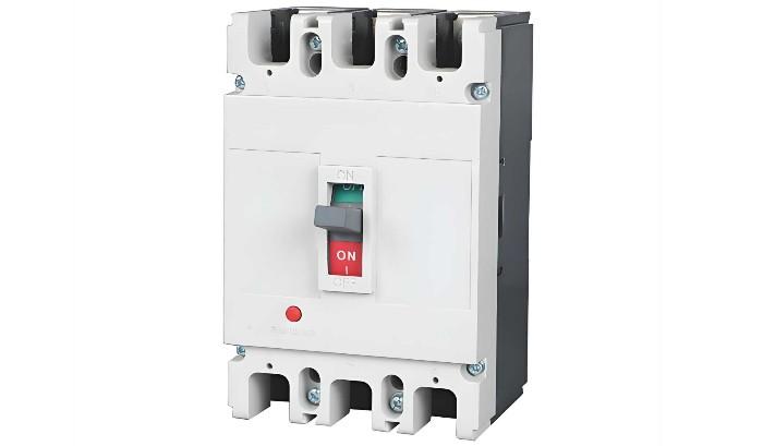
(2) Döyüşülmüş Qab Sirket Kəsəni (MCCB)
Ya da doldurma sirket kəsəni kimi tanınan, döyüşülmüş qab sirket kəsəni kontaktlar, parlaq söndürmə kameraları, kəsəclər və işləmə mekanizmləri plastic qabın içində saxlanır. Yardımcı kontaktlar, zəif voltaj kəsəcləri və paralel kəsəclər adətən modulyardır. Struktur kompakt və genelliklə təmir xidmətinə ehtiyac duymur. Dal dövrələrinin korunması üçün uyğundur. Döyüşülmüş qab kəsənləri adətən termo-maqnit kəsəclərə malikdir, amma daha böyük modeldə solid-state kəsəclər ola bilər.
MCCB-lər üçün dəyərli akım kəsəcləri elektromaqnit və elektron növlərə aid olur. Adətən, elektromaqnit MCCB-lər seçiciliklə yoxdur və yalnız uzun müddət gecikməsi və anında korunma təmin edir. Elektron MCCB-lər dörd korunma funksiyası təmin edir: uzun müddət gecikməsi, qısa müddət gecikməsi, anında və yerə bağlı short-circuit protection. Bəzi yeni təqdim edilən elektron MCCB-lərə zonaya seçici bağlanma da əlavə edilib.

Döyüşülmüş qab sirket kəsənləri adətən fütər dövrələrinin idarəetməsi və korunması, kiçik dağıtım transformatorlarının aşağı voltaj tərəfindəki başlıq anahtarlarda, sonlu enerji paylanması idarəetməsi və müxtəlif istehsal maşınlarının enerji anahtarlarda istifadə olunur.
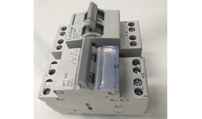
(3) Miniatur Sirket Kəsəni (MCB)
Miniatur sirket kəsəni, binaların elektrik terminali paylama sisteminin ən geniş yayılmış terminal korunma cihazıdır. Bir faza və üç fazalı dövrələrdə 125A-ya qədər short-circuit, dəyərli akım və zəif voltajdan korunmaq üçün istifadə olunur və tək pol (1P), iki pol (2P), üç pol (3P) və dörd pol (4P) konfigurasiyalarda mövcuddur.
MCB, işləmə mekanizmi, kontaktlar, korunma cihazları (müxtəlif kəsəclər) və parlaq söndürmə sistemi ilə ibarətdir. Başlıq kontaktlar əl və ya elektrik vasitəsilə bağlanır. Bağlandıqdan sonra, free-tripping mekanizmi kontaktları bağlanmış pozisyonda kilidləyir. Dəyərli akım kəsənin bobini və termal kəsənin isitici elementi başlıq dövrə ilə seriyə qoyulur, zəif voltaj kəsənin bobini isə enerji təchizatı ilə paralel qoyulur.

İqtisadi binaların elektrik layihəsində, miniatur sirket kəsənləri adətən dəyərli akım, short-circuit, dəyərli akım, voltaj itirməsi, zəif voltaj, yerə bağlı short-circuit, sızıntı, avtomatik iki enerji mənbəsinin transferi və nadir motor başlatmaq kimi korunma və idarəetmə məqsədləri üçün istifadə olunur.
Sirket Kəsənlərinin Əsas Xarakteristik Parametrləri
(1) Nominal İşləmə Voltajı (Ue)
Nominal işləmə voltajı, sirket kəsənin nominal voltajıdır, bu voltaj altında kəsən müəyyən normal xidmət və performans şərtlərində davamlı olaraq işləyə bilər.
Çinə qədər, 220kV-ə qədər voltaj səviyyələri üçün maksimum işləmə voltajı sistem nominal voltajının 1.15 dəfəsidir; 330kV və ondan yuxarı üçün maksimum işləmə voltajı nominal voltajın 1.1 dəfəsidir. Sirket kəsəni sistem maksimum işləmə voltajında isolasiya saxlamalı və bağlanmaq və kəsmək imkanı eləyib.
(2) Nominal Akım (In)
Nominal akım, tədəkkür kəsəni 40°C-dən aşağı hava temperaturunda davamlı olaraq taşıyabilən akımdır. Tənzimlənə bilən tədəkkür kəsənlər üçün, bu, tədəkkür kəsənin davamlı olaraq taşıyabiləcəyi ən yüksək akımdır.
40°C-dən yuxarı, 60°C-dan aşağı hava temperaturasında istifadə edildikdə, kəsən uzun müddət az yük ilə işləyə bilər.
(3) Dəyərli Akım Tədəkkür Ayarı (Ir)
Akim tədəkkür kəsənin Ir ayarından yüksək olduqda, sirket kəsəni gecikmə ilə işləyir. Bu, kəsənin triplənməsiz taşıyabiləcəyi ən yüksək akımdır. Bu dəyər, dövrənin ən yüksək icazə verilən akımı Iz-dən aşağı olmalıdır, lakin ən yüksək yükləmə akımı Ib-dən yüksək olmalıdır.
Termo-maqnit tədəkkür kəsənləri üçün, Ir adətən 0.7–1.0In aralığında tənzimlənə bilər. Elektron tədəkkür kəsənləri üçün, tənzimləmə aralığı genelliklə daha genişdir, 0.4–1.0In aralığında olur. Tədəkkür kəsəni tənzimlənən dəyərli akım kəsənləri olmadıqda, Ir = In.
(4) Short-Circuit Trip Current Setting (Im)
Short-circuit trip unit (instantaneous or short-time delay) causes the circuit breaker to trip quickly when high fault currents occur. Its trip threshold is Im.
(5) Rated Short-Time Withstand Current (Icw)
This is the current value allowed to pass through the conductor for a specified duration without causing damage due to overheating.
(6) Breaking Capacity
The breaking capacity of a circuit breaker refers to its ability to safely interrupt fault currents, which is not necessarily related to its rated current. Common ratings include 36kA and 50kA. It is generally divided into ultimate short-circuit breaking capacity (Icu) and service short-circuit breaking capacity (Ics).
General Principles for Circuit Breaker Selection
First, select the type and number of poles based on application; then select the rated current based on maximum operating current; finally, choose the type of trip unit and accessories. Specific requirements are as follows:
The circuit breaker’s rated operating voltage ≥ line rated voltage.
The circuit breaker’s rated short-circuit making/breaking capacity ≥ calculated load current of the line.
The circuit breaker’s rated short-circuit making/breaking capacity ≥ maximum possible short-circuit current in the line (usually calculated as RMS value).
Single-phase-to-ground short-circuit current at the end of the line ≥ 1.25 times the instantaneous (or short-time delay) trip setting of the circuit breaker.
The rated voltage of the undervoltage trip unit = line rated voltage.
The rated voltage of the shunt trip unit = control power supply voltage.
The rated operating voltage of the electric operating mechanism = control power supply voltage.
When used in lighting circuits, the instantaneous trip setting of the electromagnetic trip unit is generally 6 times the load current.
When using a circuit breaker for short-circuit protection of a single motor, the instantaneous trip setting is 1.35 times the motor starting current (for DW series) or 1.7 times (for DZ series).
When using a circuit breaker for short-circuit protection of multiple motors, the instantaneous trip setting is 1.3 times the starting current of the largest motor plus the operating currents of the remaining motors.
When using a circuit breaker as the main switch on the low-voltage side of a distribution transformer, its breaking capacity should exceed the short-circuit current on the low-voltage side of the transformer. The trip unit’s rated current should not be less than the transformer’s rated current. The short-circuit protection setting is generally 6–10 times the transformer’s rated current; the overload protection setting equals the transformer’s rated current.
After preliminarily selecting the circuit breaker type and rating, coordination with upstream and downstream protective devices is required to avoid cascading tripping and minimize accident scope.
Selectivity of Circuit Breakers
In distribution systems, circuit breakers are classified as selective or non-selective based on protection performance. Selective low-voltage circuit breakers have either two-stage or three-stage protection. Instantaneous and short-time delay characteristics are used for short-circuit protection, while long-time delay characteristics are used for overload protection. Non-selective breakers are typically instantaneous, used only for short-circuit protection, or long-time delay, used only for overload protection.
In distribution systems, if the upstream breaker is selective and the downstream breaker is non-selective or selective, selectivity is achieved by utilizing the time delay of the short-time delay trip unit or differences in time delay settings. When the upstream breaker operates with time delay, consider the following:
Regardless of whether the downstream breaker is selective or non-selective, the instantaneous overcurrent trip setting of the upstream breaker should generally be no less than 1.1 times the maximum three-phase short-circuit current at the downstream breaker’s output.
If the downstream breaker is non-selective, to prevent the upstream short-time delay overcurrent trip unit from operating first due to insufficient sensitivity of the downstream instantaneous trip unit during a short circuit, the short-time delay overcurrent trip setting of the upstream breaker should generally be no less than 1.2 times that of the downstream breaker’s instantaneous trip unit.
If the downstream breaker is also selective, to ensure selectivity, the short-time delay operating time of the upstream breaker should be at least 0.1 seconds longer than that of the downstream breaker.
Generally, to ensure selective operation between upstream and downstream low-voltage circuit breakers, the upstream breaker should preferably have a short-time delay overcurrent trip unit, and its operating current should be at least one level higher than that of the downstream trip unit. At minimum, the upstream operating current Iop.1 should be no less than 1.2 times the downstream operating current Iop.2, i.e., Iop.1 ≥ 1.2Iop.2.
Cascading Protection of Circuit Breakers
In distribution system design, coordination between upstream and downstream circuit breakers must achieve "selectivity, speed, and sensitivity." Selectivity relates to coordination between breakers, while speed and sensitivity are associated with the characteristics of the protective device and the operating mode of the circuit.
Proper coordination between upstream and downstream breakers enables selective isolation of the faulty circuit, ensuring other non-faulty circuits continue normal operation. Poor coordination affects system reliability.
Cascading protection is a practical application of the current-limiting characteristics of circuit breakers. Its main principle is to utilize the current-limiting effect of the upstream breaker (QF1), which allows selection of a downstream breaker (QF2) with lower breaking capacity, thus reducing cost. The current-limiting upstream breaker QF1 can interrupt the maximum prospective short-circuit current at its installation point. Since the upstream and downstream breakers are connected in series, when a short circuit occurs at the output of the downstream breaker QF2, the actual short-circuit current is significantly reduced by the current-limiting effect of QF1, far below the prospective short-circuit current at that point. Thus, the breaking capacity of QF2 is effectively enhanced by QF1, exceeding its rated breaking capacity.
Cascading protection has certain conditions: for example, adjacent circuits should not have critical loads (since tripping of QF1 would also de-energize QF3’s circuit), and the instantaneous settings of QF1 and QF2 must be properly matched. Cascading data can only be determined experimentally, and coordination between upstream and downstream breakers must be provided by the manufacturer.
Sensitivity of Circuit Breakers
To ensure reliable operation of the instantaneous or short-time delay overcurrent trip unit under minimum system operating conditions and during the mildest short-circuit fault within its protection range, the sensitivity of the circuit breaker must meet the requirements of the "Low-Voltage Electrical Distribution Design Code" (GB50054-95), which specifies a sensitivity of no less than 1.3, i.e., Sp = Ik.min / Iop ≥ 1.3. Here, Iop is the operating current of the instantaneous or short-time delay overcurrent trip unit, Ik.min is the single-phase or two-phase short-circuit current at the end of the protected line under minimum system operating conditions, and Sp is the sensitivity of the circuit breaker.
When selecting a circuit breaker, its sensitivity should also be verified. For selective breakers with both short-time delay and instantaneous overcurrent trip units, only the sensitivity of the short-time delay trip unit needs to be checked; the sensitivity of the instantaneous trip unit does not require verification.
Selection and Setting of Circuit Breaker Trip Units
(1) Setting of Instantaneous Overcurrent Trip Unit Operating Current
Some electrical equipment protected by the circuit breaker has high peak currents during startup, several times the rated current, causing the breaker to experience high peak currents briefly. The operating current Iop(o) of the instantaneous overcurrent trip unit must exceed the circuit’s peak current Ipk, i.e., Iop(o) ≥ Krel·Ipk, where Krel is the reliability factor. When selecting a circuit breaker, ensure its instantaneous overcurrent trip setting exceeds the peak current to prevent nuisance tripping.
(2) Setting of Short-Time Delay Overcurrent Trip Unit Operating Current and Time
The operating current Iop(s) of the short-time delay overcurrent trip unit should also exceed the circuit’s peak current Ipk, i.e., Iop(s) ≥ Krel·Ipk, where Krel is the reliability factor. Short-time delay trip times are generally 0.2s, 0.4s, or 0.6s, determined based on selectivity with upstream and downstream protection devices, ensuring the upstream device operates later than the downstream by one time step.
(3) Setting of Long-Time Delay Overcurrent Trip Unit Operating Current and Time
The long-time delay overcurrent trip unit is primarily used for overload protection. Its operating current Iop(l) only needs to exceed the circuit’s maximum load current (calculated current I30), i.e., Iop(l) ≥ Krel·I30, where Krel is the reliability factor. The operating time should exceed the duration of allowable short-term overloads to prevent nuisance tripping.
(4) Coordination Requirements Between Overcurrent Trip Unit Operating Current and Protected Circuit
To prevent insulation damage or fire due to overloads or short circuits without the circuit breaker tripping, the overcurrent trip unit’s operating current Iop must satisfy the condition: Iop ≤ Kol·Ial. Here, Ial is the allowable current-carrying capacity of the insulated cable; Kol is the allowable short-term overload factor—typically 4.5 for instantaneous and short-time delay trip units, 1.1 for long-time delay trip units used for short-circuit protection, and 1.0 when used only for overload protection. If this coordination requirement is not met, the trip unit setting should be adjusted, or the conductor or cable cross-section should be increased appropriately.


