Mechanical Endurance Testing
The mechanical endurance of circuit breakers is tested according to IEC 62271-100, requiring 10,000 operations (M2 class). During testing at an overseas laboratory, the first prototype failed at 6,527 operations due to a trip spring fracture. The lab accepted this isolated failure, attributing it to spring installation issues. A second prototype was tested but similarly failed after over 6,000 operations due to another trip spring breakage. Consequently, the test lab only issued a mechanical endurance report for 2,000 operations (M1 class).
Root Cause Analysis: The fracture originated from machine-hammering marks at the spring's bending point during manufacturing, creating a weak spot that failed after thousands of operations. Although the 36 kV circuit breaker only achieved an M1-class (2,000 operations) mechanical endurance rating, the high authority and credibility of the KEMA test report—valid for both 50/60 Hz and grounded/ungrounded systems—enabled successful sales in Latin America, Europe, Southeast Asia, and other global markets.
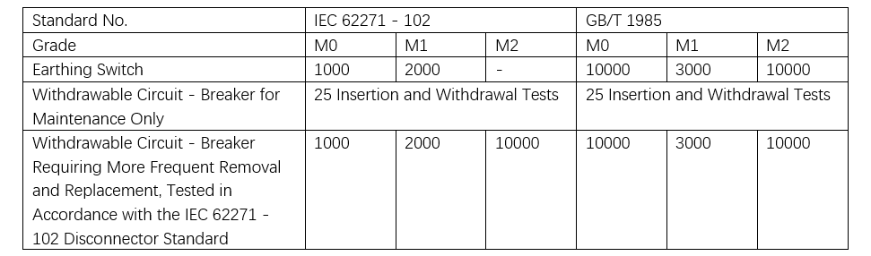
For earthing switches and withdrawable circuit breakers, differences in mechanical durability testing are shown in Table 1. Generally, IEC customers accept that withdrawable circuit breaker trolleys are used only for maintenance. Thus, compliance with international customer requirements can be met by performing only 25 insertion and withdrawal cycles as specified in IEC 62271-200, clause 6.102.1.
Verification of Switching and Closing Capability
Switching and closing tests for circuit breakers are conducted in several configurations depending on application: standalone (unhoused) circuit breakers, withdrawable circuit breakers mounted in test equipment, or withdrawable circuit breakers installed in switchgear. When switchgear and circuit breaker are tested together, the switching and closing tests are performed within the assembled switchgear. For standalone type tests, it is recommended to provide a dedicated withdrawable compartment for testing.
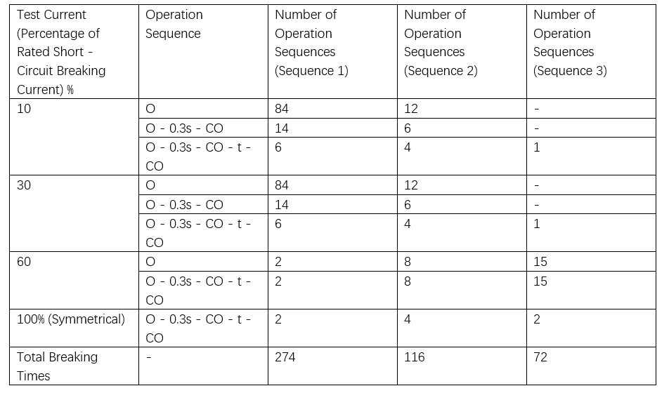
IEC switching tests for circuit breakers define various test sequences. Customers may select different sequences. For example, Sequence 1 consists of 274 breaking operations (130 T10, 130 T30, 8 T60, and 6 T100s). To improve cost and time efficiency—since test labs charge based on test duration—customers often opt for Sequence 3, totaling 72 operations (3 T10/T30, 60 T60, and 6 T100s). Although the number of operations is reduced, the total energy is increased. However, compared to the full-capacity 50-break test standard commonly used domestically, the IEC test remains significantly less severe. Table 2 outlines the switching operation counts defined in IEC 62271-100 for endurance testing.
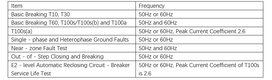
For circuit breakers intended for both 50 Hz and 60 Hz applications, the STL guideline specifies testing frequencies as shown in Table 3 to validate suitability and issue a type test report. To meet dual-frequency requirements, only basic switching tests (E1 class) at both 50 Hz and 60 Hz are required. The endurance test can be performed at either 50 Hz or 60 Hz. Similarly, the O–0.3 s–CO–15 s–CO sequence test requires only basic testing. While test requirements vary for different neutral grounding systems, this does not affect the endurance test.
Internal Arc Testing
Test Voltage: As per IEC 62271-200, Annex AA.4.2, the test shall be performed at any suitable voltage not exceeding the rated voltage. If a voltage lower than the rated voltage is selected, the following conditions must be met:
a) The calculated average RMS test current must satisfy the current requirements in AA.4.3.1;
b) The arc must not extinguish prematurely at any stage.
Temporary single-phase extinction is permitted if the cumulative duration of current interruptions does not exceed 2% of the total test duration, and no single interruption lasts longer than the next expected current zero. The integral of the AC current component must be at least equal to the value specified in AA.4.3.1.
According to the STL guideline, during three-phase and two-phase arc tests, the two phases may be supplied by a current source at a voltage below the rated value, while the third phase is supplied by a separate voltage source at Ur/√3. In single-phase tests, the arc must be initiated between the middle phase and ground. The circuit may be supplied by a current source at a voltage below the rated value, provided the voltage source has sufficient short-circuit power to clearly detect voltage breakdown and distinguish it from interference.
For a 17.5 kV switchgear, the internal arc fault test is performed at 7.1 kV, which is documented in the test report.
Test Conditions and Equipment Layout:
It is permissible to conduct sequential tests on different untested sections of a single unit. The laboratory is not responsible for providing or arranging cable ducts. The test arrangement must be detailed in the test report. If a functional unit type is not intended to be used as an end unit under service conditions, during testing, two or more functional units should be arranged in the assembly, placing the tested unit as close as possible to the side and away from the simulated room wall.
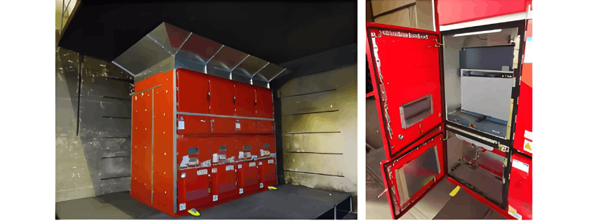
The ceiling must be at least 200 mm ± 50 mm above the test object. The pressure relief panel's opening path must not strike the ceiling. Test results are valid for all distances between the test object and ceiling greater than the test setup distance. The test sample must be tested in its actual operating configuration. For switchgear with hinged ventilation flaps, removable operating handles need not be installed, but the flap must be in the open position during the internal arc test. As shown in Figure 4, the internal arc test setup for a 17.5 kV switchgear involves four switchgear units in a row. Testing is conducted on the three high-voltage compartments of the leftmost end unit. The top of the cabinet is 600 mm below the ceiling, with a reflector plate installed to prevent arc reflection from the ceiling and burning of horizontal indicators. A test isolator trolley replaces the circuit breaker for testing, and the internal protective plate at the lower ventilation door is in the open position.
Additional Notes on IEC Testing
IEC tests result in separate type test certificates for different test items, including:
Type test certificate for insulation performance
Type test certificate for short-circuit making and breaking performance
Type test certificate for internal arc performance
The following drawings and manufacturer's documentation must be provided to demonstrate consistency between the tested switchgear and the supporting design drawings. The test lab will verify the sample by measuring and checking drawings, busbar specifications, support spacing, etc., against the provided documentation. Any deviations are recorded.
a) Single-line diagram of the switchgear and controlgear, including component type names.
b) General arrangement drawing (assembly drawing), including:
Overall dimensions
Busbar system dimensions
Support structure
Electrical clearances
Materials of major components
c) Switchgear identification drawings as detailed in the relevant STL guidelines.