Difference Between RTD and Thermocouple

08/26/2025

RTDs and Thermocouples: Key Temperature Sensors

Resistance Temperature Detectors (RTDs) and thermocouples are two fundamental types of temperature sensors. While both serve the primary function of measuring temperature, their operational principles differ significantly.

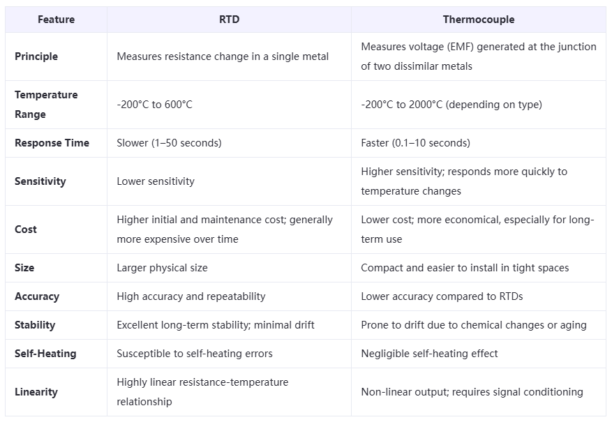
An RTD relies on the predictable change in electrical resistance of a single metal element as temperature varies. In contrast, a thermocouple operates based on the Seebeck effect, where a voltage difference (electromotive force, EMF) is generated at the junction of two dissimilar metals, and this voltage corresponds to the temperature difference.

Beyond these two, other common temperature sensing devices include thermostats and thermistors. Temperature sensors, in general, function by detecting physical changes—such as resistance or voltage—that correlate with thermal energy within a system. For instance, in an RTD, resistance changes reflect temperature variations, while in a thermocouple, changes in EMF indicate temperature shifts.

Below, we explore the key differences between RTDs and thermocouples, extending beyond their basic operating principles.

Definition of RTD

RTD stands for Resistance Temperature Detector. It determines temperature by measuring the electrical resistance of a metallic sensing element. As temperature increases, the resistance of the metal wire rises; conversely, it decreases as temperature falls. This predictable resistance-temperature relationship allows accurate temperature measurement.

Metals with well-characterized resistance-temperature curves are typically used in RTD construction. Common materials include copper, nickel, and platinum. Platinum is most widely used due to its excellent stability and linearity over a broad temperature range (typically -200°C to 600°C). Nickel, while less expensive, exhibits non-linear behavior above 300°C, limiting its use.

Definition of Thermocouple

A thermocouple is a thermoelectric sensor that generates a voltage in response to temperature differences via the thermoelectric (Seebeck) effect. It consists of two dissimilar metal wires joined at one end (the measuring junction). When this junction is exposed to heat, a voltage is produced proportional to the temperature difference between the measuring junction and the reference (cold) junction.

Different metal combinations yield different temperature ranges and output characteristics. Common types include:

  • Type J (Iron-Constantan)
  • Type K (Chromel-Alumel)
  • Type E (Chromel-Constantan)
  • Type B (Platinum-Rhodium)

These standardized types allow thermocouples to operate over a wide range, typically from -200°C to over 2000°C, making them suitable for high-temperature applications. Thermocouples are also known as thermoelectric thermometers.

Key Differences Between RTD and Thermocouple

Conclusion

Both RTDs and thermocouples offer distinct advantages and limitations, making them suitable for different applications. RTDs are preferred where high accuracy, stability, and repeatability are critical, such as in laboratory and industrial process control. Thermocouples are ideal for applications requiring wide temperature ranges, fast response, and cost-effectiveness, particularly in high-temperature environments. The choice between the two ultimately depends on the specific requirements of the application, including temperature range, accuracy, response time, and budget.

Hello,I'm Wdwiin. A decade of hands-on experience in electrical engineering, specializing in high-voltage systems, smart grids, and renewable energy technologies. Passionate about technical exchange and knowledge sharing, committed to interpreting industry trends with professional insights to empower peers. Connection creates value—let’s explore the boundless possibilities of the electrical world together!

What is the difference between a dielectric and an insulator?
Dielectrics and insulators are distinguished primarily by their applications. One of the main differences is that a dielectric can store electrical energy by becoming polarized in an electric field, whereas an insulator resists the flow of electrons to prevent current conduction. Other key differences between them are outlined in the comparison chart below.Definition of DielectricA dielectric material is a type of insulator that contains few or no free electrons. When subjected to an electric fi
08/30/2025
What losses occur during operation of the transformer? How to reduce losses?
Transformers experience various types of losses during operation, primarily categorized into two main types: copper losses and iron losses.Copper LossesCopper losses, also known as I²R losses, are caused by the electrical resistance of the transformer windings—typically made of copper. As current flows through the windings, energy is dissipated in the form of heat. These losses are proportional to the square of the load current (I²R), meaning they increase significantly with high
Rockwell
08/29/2025
Cable Fault Detection, Testing, Location and Repair
I. Methods for Cable Testing and Inspection:Insulation Resistance Test: Use an insulation resistance tester to measure the insulation resistance value of the cable. A high insulation resistance value indicates good insulation, while a low value may suggest insulation problems requiring further investigation.Voltage Withstand Test: Apply a high-voltage test using a high-voltage tester to verify whether the cable can withstand high voltage under its rated operating conditions. Under normal circums
08/29/2025
Cable Quality Inspection and Cable Detection & Testing
Power cable quality inspection and cable testing are conducted to ensure that the cable's quality and performance meet specified requirements, thereby guaranteeing the safe and stable operation of power systems. Below are some common contents of power cable quality inspection and cable testing:Visual Inspection: Check the cable surface for physical defects such as damage, deformation, or scratches to ensure the cable's exterior is intact.Dimensional Measurement: Measure dimensional parameters su
08/29/2025
Inquiry
Download
IEE-Business is dedicated to serving the personnel in the global power industry.
Join IEE-Business, not only can you discover power equipment and power knowledge, but also canhnd like - minded friends!