RTDs vs Thermocouples | Key Differences & Applications

RTDs and Thermocouples: Key Temperature Sensors
Resistance Temperature Detectors (RTDs) and thermocouples are two fundamental types of temperature sensors. While both serve the primary function of measuring temperature, their operational principles differ significantly.
An RTD relies on the predictable change in electrical resistance of a single metal element as temperature varies. In contrast, a thermocouple operates based on the Seebeck effect, where a voltage difference (electromotive force, EMF) is generated at the junction of two dissimilar metals, and this voltage corresponds to the temperature difference.
Beyond these two, other common temperature sensing devices include thermostats and thermistors. Temperature sensors, in general, function by detecting physical changes—such as resistance or voltage—that correlate with thermal energy within a system. For instance, in an RTD, resistance changes reflect temperature variations, while in a thermocouple, changes in EMF indicate temperature shifts.
Below, we explore the key differences between RTDs and thermocouples, extending beyond their basic operating principles.
Definition of RTD
RTD stands for Resistance Temperature Detector. It determines temperature by measuring the electrical resistance of a metallic sensing element. As temperature increases, the resistance of the metal wire rises; conversely, it decreases as temperature falls. This predictable resistance-temperature relationship allows accurate temperature measurement.
Metals with well-characterized resistance-temperature curves are typically used in RTD construction. Common materials include copper, nickel, and platinum. Platinum is most widely used due to its excellent stability and linearity over a broad temperature range (typically -200°C to 600°C). Nickel, while less expensive, exhibits non-linear behavior above 300°C, limiting its use.
Definition of Thermocouple
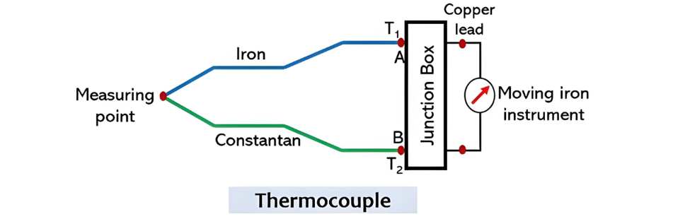
A thermocouple is a thermoelectric sensor that generates a voltage in response to temperature differences via the thermoelectric (Seebeck) effect. It consists of two dissimilar metal wires joined at one end (the measuring junction). When this junction is exposed to heat, a voltage is produced proportional to the temperature difference between the measuring junction and the reference (cold) junction.
Different metal combinations yield different temperature ranges and output characteristics. Common types include:
Type J (Iron-Constantan)
Type K (Chromel-Alumel)
Type E (Chromel-Constantan)
Type B (Platinum-Rhodium)
These standardized types allow thermocouples to operate over a wide range, typically from -200°C to over 2000°C, making them suitable for high-temperature applications. Thermocouples are also known as thermoelectric thermometers.
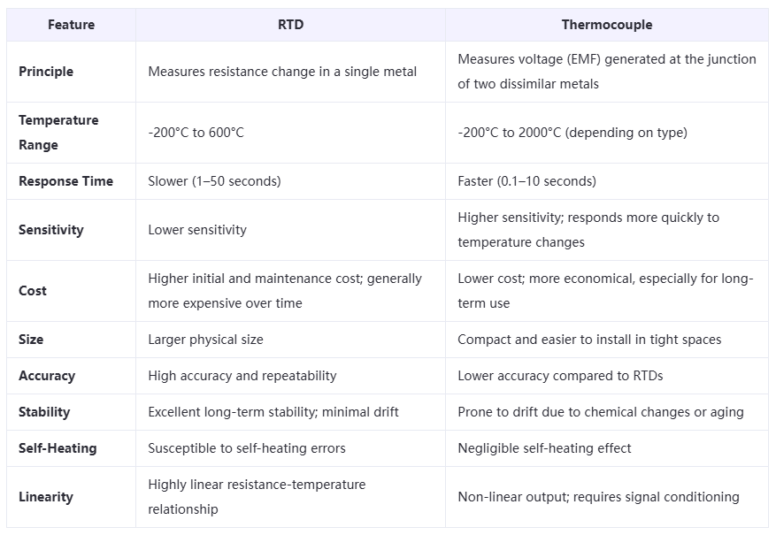
Key Differences Between RTD and Thermocouple
Conclusion
Both RTDs and thermocouples offer distinct advantages and limitations, making them suitable for different applications. RTDs are preferred where high accuracy, stability, and repeatability are critical, such as in laboratory and industrial process control. Thermocouples are ideal for applications requiring wide temperature ranges, fast response, and cost-effectiveness, particularly in high-temperature environments. The choice between the two ultimately depends on the specific requirements of the application, including temperature range, accuracy, response time, and budget.