The Necessity of Power Distribution System Maintenance

08/23/2025

Fault Phenomenon

A power distribution system fault occurred in a customer's server room, resulting in damage to some IT equipment and instruments. Upon receiving the feedback, our company's engineers immediately rushed to the site to inspect the power distribution system and analyze the cause of the fault.

Fault Inspection

The server room uses a three-phase five-wire power supply system. Two three-phase input, three-phase output UPS units (without output isolation transformers) are operating in parallel to power the IT equipment in the room. Both the UPS input and output circuit breakers are controlled using 4-pole (4P) breakers.

Upon inspection of the damaged IT equipment, it was found that all affected devices and instruments were connected to the load side of the UPS output phase C, while equipment connected to phases A and B were operating normally. Further inspection revealed that the neutral wire (zero line) on the UPS input circuit breaker was loose, causing the neutral line to become disconnected (floating) on the downstream side of the UPS.

Fault Analysis

In a three-phase five-wire power supply system, when the neutral line is broken, single-phase loads lose their return path, creating phase voltage at the break point, which poses a risk to personal safety. If the three-phase loads are unbalanced, the neutral point will shift, causing the voltage on each phase to either increase or decrease. According to the principle of voltage division in a series circuit, because phase C had a lighter load, it acquired the highest voltage, approaching the 380V line voltage, which led to the destruction of equipment on that phase.

Severe three-phase load imbalance, combined with overheating of the distribution system circuit breakers and loose wiring terminals, created a latent fault that was not promptly eliminated. This led to poor contact on the neutral line, causing sparking, heating, oxidation, and ultimately complete disconnection.

Additionally, the use of 4P circuit breakers for both UPS input and output means that when the UPS input breaker is opened (for example, during battery discharge maintenance), the neutral line is also cut off, which can similarly cause equipment failure.

Summary

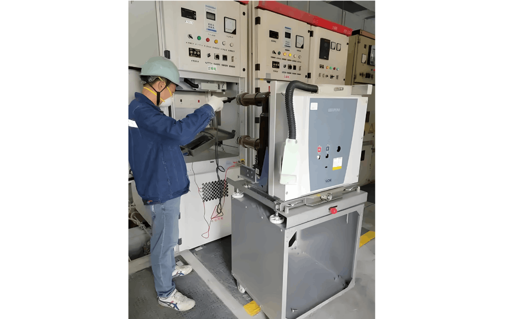
The server room's power distribution system requires regular inspection and maintenance by qualified personnel in the following aspects:

  • Measure whether circuit breakers, cables, and terminal connections are overheating.
  • Check if instrument displays are functioning normally.
  • For UPS three-phase output power supply, the load on each phase should be distributed as evenly as possible to maintain three-phase load balance. Strengthen monitoring of three-phase currents and make timely adjustments upon detecting imbalance.
  • Measure whether the line current is within the safe operating range of the circuit breakers.
  • The cross-sectional area of the neutral and ground wires must not be less than the minimum specified by national standards, and connections must be secure and reliable.
  • Fuses or individual switching devices must not be installed on the neutral line.
  • When disconnecting a three-phase four-wire circuit, the phase (live) conductors should be disconnected first, followed by the neutral conductor. The reverse order should be followed when reconnecting.
  • Functional labels for all components must be accurate and clear.

Hello! I'm Leon, with 20 years of extensive experience in the power industry. My expertise spans from power distribution equipment to grid operations and maintenance, grounded in robust hands-on and theoretical knowledge. Currently, I focus on sharing insights into electrical equipment fault diagnosis, demystifying complex technical challenges through accessible explanations. I welcome collaboration with industry peers and enthusiasts to collectively explore the intricacies of the power sector.

What is the difference between a dielectric and an insulator?
Dielectrics and insulators are distinguished primarily by their applications. One of the main differences is that a dielectric can store electrical energy by becoming polarized in an electric field, whereas an insulator resists the flow of electrons to prevent current conduction. Other key differences between them are outlined in the comparison chart below.Definition of DielectricA dielectric material is a type of insulator that contains few or no free electrons. When subjected to an electric fi
08/30/2025
Fault Analysis and Treatment of Oil-Immersed Transformers
Oil Leakage at Welded JointsOil leakage at welded joints primarily stems from poor welding quality, such as incomplete or detached welds, and defects like pinholes and gas pores. Although oil-immersed transformers are initially coated with solder and paint during manufacturing, potentially masking these issues temporarily, the defects tend to surface during operation. Additionally, electromagnetic vibration can cause weld cracks, leading to oil leakage.To resolve such leaks, the first critical s
08/29/2025
What losses occur during operation of the transformer? How to reduce losses?
Transformers experience various types of losses during operation, primarily categorized into two main types: copper losses and iron losses.Copper LossesCopper losses, also known as I²R losses, are caused by the electrical resistance of the transformer windings—typically made of copper. As current flows through the windings, energy is dissipated in the form of heat. These losses are proportional to the square of the load current (I²R), meaning they increase significantly with high
Rockwell
08/29/2025
Cable Fault Detection, Testing, Location and Repair
I. Methods for Cable Testing and Inspection:Insulation Resistance Test: Use an insulation resistance tester to measure the insulation resistance value of the cable. A high insulation resistance value indicates good insulation, while a low value may suggest insulation problems requiring further investigation.Voltage Withstand Test: Apply a high-voltage test using a high-voltage tester to verify whether the cable can withstand high voltage under its rated operating conditions. Under normal circums
08/29/2025
Inquiry
Download
IEE-Business is dedicated to serving the personnel in the global power industry.
Join IEE-Business, not only can you discover power equipment and power knowledge, but also canhnd like - minded friends!