
Wakati wa kazi halisi, mabadiliko ya joto yanayofanikiwa kwenye transforma zinazokuwa na pad ni:
Kutokana na kuboresha utafutaji wa moto, hii karatasi hutumia utafiti wa anasimuli ili kujenga modeli ya tatu ya transforma. Kwa kutathmini maeneo ya moto, inachukua nyuzi za moto na kuboresha muundo wa mfumo wa upimaji.
1. Msingi wa Nyuzi ya Moto
Nyuzi ya moto hutoa mabadiliko ya joto ya muda na namba, na kuunda moto, kutembelea na kubainisha moto vilivyo vinavyovikana. Kwa transforma zinazokuwa na pad, moto unatoka kwenye cores, windings, na vyenyingi. Mazingira ya kazi na muda wanaweza kubadilisha vitendo vya moto, na miamala mingine (cores, windings, insulation) kunaweka viwango mbalimbali vya joto.
Moto unatembelea kwa conduction (kubwa, kuchelewesha moto kutoka windings/cores kwa amboni rasini hadi hewa ya kimataifa) na convection. Ukuaji wa conduction unategemea na gradienti za joto—moto unatoka sehemu zenye joto kwa rasini yenye joto chache, kisha kuharibika kwenye hewa ya nje. Hisabati za flux za moto zinavyofuatilia:

Katika formula: q inahifadhi ukubwa wa flux ya moto; λ inahifadhi ufanisi wa moto; ∂t/∂x ni gradienti ya joto, inarejelea kiwango cha mabadiliko ya joto na umbali; n ni kifanya kwa moto. Waktu una viwango tofauti vya joto, moto unatumia sana kuboresha joto, na hali hii ya kuboresha joto ni convection. Wakati transforma zinazokuwa na pad zinakufanya kazi, moto unaojengwa kutoka sehemu mbalimbali unaweza kutumiana na hewa na kutelekeleza kati yao, kusababisha mabadiliko katika joto la hewa ya karibu. Katika hii, moto unatumia sana kutelekeleza, ambayo inaweza kutafsiriwa kwa formula ifuatayo:

Katika formula, h ni ufanisi wa tembeleo wa moto, tf inahifadhi joto la fluid, na tw inahifadhi joto la uwanda wa vitu. Waktu joto la chochote ni juu zaidi ya sifuri, moto wa radiance unaweza kutengenezwa, mara nyingi inatafsiriwa kama moto wa joto. Waktu viwango vingine vinavyobaki vya sababu, kiasi cha radiance kinaweza kubadilika kulingana na joto linavyopanda (na joto linalozingatia mkakati wa pande). Wakati transforma zinazokuwa na pad zinakufanya kazi, vifaa bila kutumia radiance ya moto; wakati joto la transforma lipambana, fanya kazi ya radiance itakuwa kuboresha joto kwa radiance, na hii inaweza kutafsiriwa kwa formula ifuatayo:

Katika formula, S inahifadhi eneo la radiance, T ni joto thermodynamic, na σ ni sababu ya radiance. Waktu kutengeneza mfumo wa upimaji kwa transforma zinazokuwa na pad, njia ya utafiti wa anasimuli (FEA) inatumika kubuni equations ya thermal equilibrium. Kwa kutathmini, joto kwenye node yoyote ya chochote linaweza kutathminika. Hii ni muhimu sana kwa kutathmini vipimo vya joto vivyotegemeana, kupata nyuzi bora za joto, na kisha kutathmini miongozo. Miundombinu msingi ya kutengeneza nyuzi ya joto kwa FEA ni ifuatayo:
Kupinda domain ya fiziki ya tatu;
Tumia functions kutaja mabadiliko ya joto kwenye node yoyote;
Jenga equations ya elementi;
Paka elementi na tumia excitations za nje kwenye node;
Solve equations kwa kutathmini boundaries ya nyuzi ya joto;
Hesabu uzito wa joto kwenye node yoyote;
Tengeneza uzito wa joto wa elementi kutokana na equations za nyuzi ya joto.
2 Modeling and Temperature Field Simulation of Pad - Mounted Transformers
2.1 Finite Element Modeling
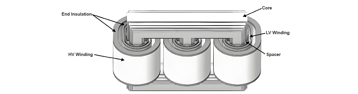
Meza 1 inajaribu parameta tofauti za transforma zinazokuwa na pad zinazochaguliwa katika karatasi hii. Modeli ya anasimuli imetengenezwa kulingana na parameta hizi. Baada ya hii, models zisizotumika zimeundwa kwa high - voltage winding, low - voltage winding, na iron core za transforma zinazokuwa na pad.
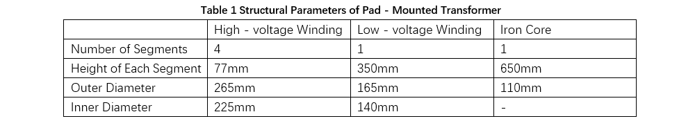
Wakati wa kutengeneza modeli, kwa sababu mifano ya high - voltage winding outlet terminals zinafanyika vizuri, hazitachaguliwa katika hatua ya kwanza ya unda. Kwa kutenganisha, iron core imeundwa kama structure moja, na inter - laminar gaps zimezuiwa (hizi zimeundwa kwa kutumia properties za bulk silicon steel kusababisha conductivity).
Ili kutathmini athari za natural convection kwa upimaji, domain ya external air (na ukubwa wa 5000mm×5000mm×3000mm) imeongezwa kwenye mazingira ya simulation, kusaidia kutengeneza mazingira ya kweli ya airflow zinazokuruka kwenye transforma.
2.2 Enclosure Model of Pad-Mounted Transformer
Windings na iron core zimetengenezwa kama heat sources, na hitimisho yao ya moto yanahesabiwa kulingana na parameta za design za transforma. Domain ya hewa imeconfigure na pressure outlets kwenye pembeni msaani na inlets zinazowekwa kwenye pembeni chini na sides, kudumisha temperature ya ambient set kwenye 300K. Wakati wa simulations, natural convection parameters zinapata kutokana na kuchagua turbulence model sahihi kulingana na Rayleigh number.
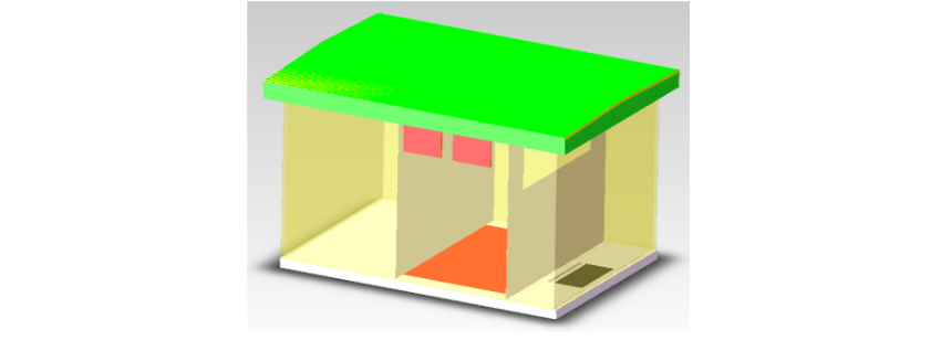
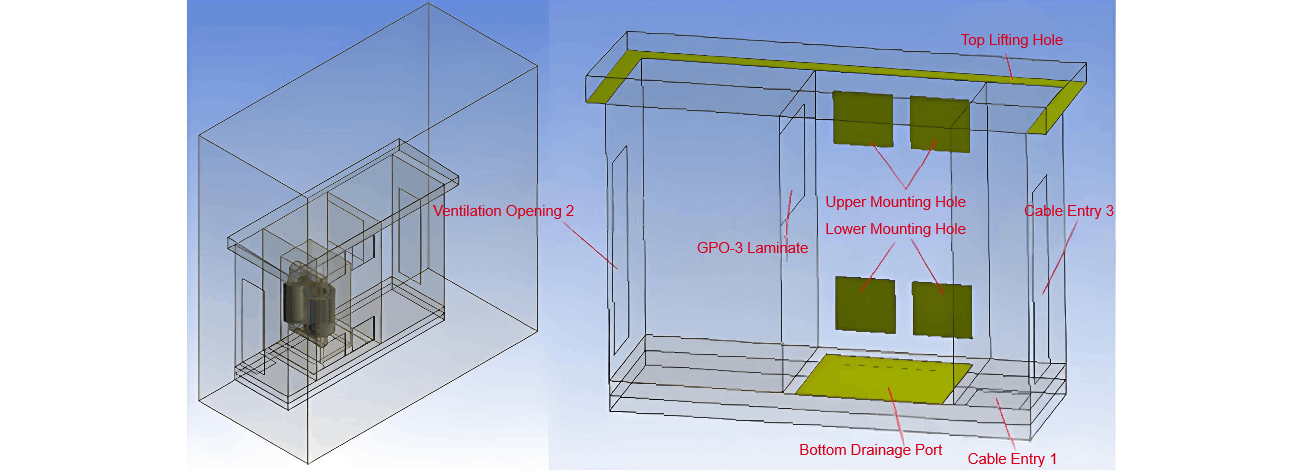
Geometry ya enclosure (Figure 2) imeunganishwa kwa sababu ya composite structure yake complex. Perforated panels za roof zimezuiwa, kutathmini kabisa kama domain ya hewa. Porous media zimezuiwa chini ya eaves kusimulia resistance ya flow. Domain ya hewa kwenye bottom support beams zimeangalia kama interconnected. Air layer ya 155mm-high imeongezwa chini ya enclosure kusaidia impact ya foundation kwa upimaji.
Katika modeli iliyoundwa, pre-set bottom holes, top holes, na upper-lower holes zote zinazozunguka porous media, na thickness ya 10 mm (kama yellow-green block katika Figure 3), kusimulia mesh plate. Specification ya bottom hole ni 1450 × 1200 mm², na specification ya upper-lower holes ni 550 × 500 mm². Three openings na epoxy plate zimeundwa pia katika model, na openings zinapatikana kwa hali ya open au closed kulingana na hali ya kweli. Mara nyingi, ikiwa floor-mounted type itachaguliwa, top hole, epoxy plate, na Opening 1 zitakuwa hali ya open; ikiwa bottom-holed type itachaguliwa, top hole, bottom hole, na Openings 1/2/3 zitakuwa zote hali ya open.
2.3 Temperature Field Distribution Analysis
Baada ya hii, modeli ya anasimuli imeundwa kwa kutengeneza geometric model. Hakikisha unity ya natural convection na internal mesh models, na refine meshing kwenye enclosure holes na air interfaces kuboresha accuracy ya hisabati. Kulingana na geometric model, modeli ya anasimuli ina nodes 401,856 na meshes 518,647. Key settings kwa modeli ya pad-mounted transformer:
Kutumia software ya anasimuli, modeli ya temperature field inatoa: Windings ni chenye joto cha juu zaidi katika transforma, followed by the iron core; adjacent air temperature is also high, decreasing during air rise until matching ambient temperature at the pressure outlet. During operation, hot air expansion causes air accumulation and collisions between ambient and duct air (due to continuous heating and volume increase). Air viscosity affects duct flow and the flow field. Hot air accelerates near the ground and slows away; airflow-surface contact forms a thermal boundary layer, which, due to its thickness, reduces heat transfer coefficients, increasing temperature and air viscosity while decreasing flow velocity. Hot air alters the temperature above the transformer, with temperature proportional to thermal radiation.
3 Heat Dissipation Design of Pad - Mounted Transformers
3.1 Model Analysis
Pad-mounted transformers are arranged inside enclosures with a high safety level. To ensure smooth air circulation within the enclosure and give full play to the transformer's heat dissipation performance, axial flow fans need to be configured to discharge hot air from the equipment interior. Meanwhile, heat sinks are installed outside the enclosure to achieve heat exchange. Through heat exchange, the continuous circulation of air inside the transformer can be promoted.
During the operation of pad-mounted transformers, heat is mainly generated by windings and iron cores. Therefore, the design needs to focus on the air flow states of these two components and integrate the relevant elements for building the heat dissipation model.
3.2 Determination of Model Parameters
For pad-mounted transformers, the differences between indoor air parameters and temperature performance parameters are relatively small. When selecting silicon steel sheets, their heat resistance performance should be prioritized. Meanwhile, the numerical ratio of copper wires to insulating resin is analyzed to determine the thermal performance parameters.
3.3 Condition Setting
The average pressure at the air inlet and outlet of the pad-mounted transformer is one atmospheric pressure. Combined with the performance of the heat sink, the temperature of cold air is taken as the inlet condition to establish a finite element model, and the symmetry plane and air inlet-outlet direction are defined.
3.4 Result Analysis
After establishing the model and setting the boundary conditions, calculations are carried out. The analysis shows that the air outlet of the pad-mounted transformer is the hottest point, with a temperature reaching 394.5K (corresponding to a hot-spot temperature of 120.5℃). The hottest point of the iron core is far from the air outlet, and the calculated hot-spot temperature is 110℃. Moreover, the positions close to the air inlets and outlets have poor heat dissipation performance.
3.5 Inlet and Outlet Air Analysis
Simulate the change of air flow velocity: If the hot high-voltage winding is built-in close to the air outlet and the air outlet has a right-angle structure, it will affect the air pressure, making the air inside the encapsulation thin and unfavorable for heat dissipation.
Based on this, optimize the air outlet design: Move the air outlet upward by about 30cm, keep the height unchanged, and simultaneously reduce the width of the air inlet (mainly reduce by 10cm), so that the overall length of the enclosure increases by 20cm. After calculation, under this scheme, the hot-spot temperature and average temperature of the winding decrease significantly. Analyzing the air flow field velocity distribution, the winding air flow shows a 120° angle when transferred to the air outlet, indicating that the air flow is smooth.
3.6 Summary
Pad-mounted transformers play a crucial role in the power distribution system. If the large amount of heat generated during operation cannot be dissipated in a timely manner, it is likely to cause failures and threaten the stability of the system. Designers need to deeply analyze the heat dissipation problems of pad-mounted transformers, combine with the changes of the temperature field, use scientific methods such as the finite element method to build heat dissipation models, optimize the equipment's heat dissipation system, and improve the overall heat dissipation efficiency.


