Theory of Transformer on Load and No Load Operation

05/06/2024

image.png

We have discussed about the theory of ideal transformer for better understanding of actual elementary theory of transformer. Now we will go through the practical aspects one by one of an electrical power transformer and try to draw vector diagram of transformer in every step. As we said that, in an ideal transformer; there are no core losses in transformer i.e. loss free core of transformer. But in practical transformer, there are hysteresis and eddy current losses in transformer core.

Theory of Transformer on No-Load

Having No Winding Resistance and No Leakage Reactance

Let us consider one electrical transformer with only core losses, which means, it has only core losses but no copper loss and no leakage reactance of transformer. When an alternating source is applied in the primary, the source will supply the current for magnetizing the core of transformer.

But this current is not the actual magnetizing current; it is a little bit greater than actual magnetizing current. Total current supplied from the source has two components, one is the magnetizing current which is merely utilized for magnetizing the core, and another component of the source current is consumed for compensating the core losses in transformers.

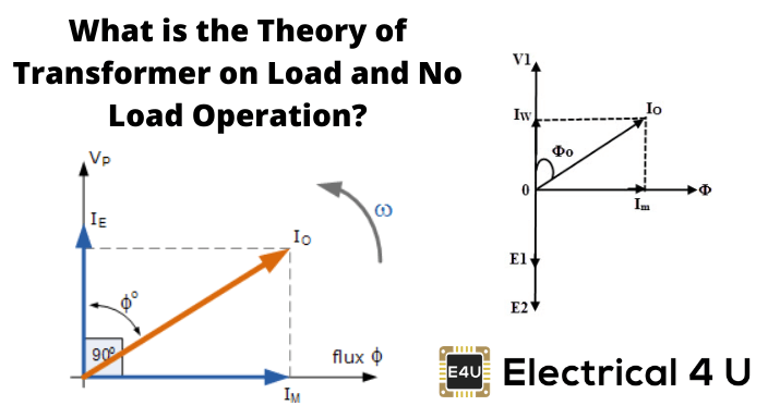
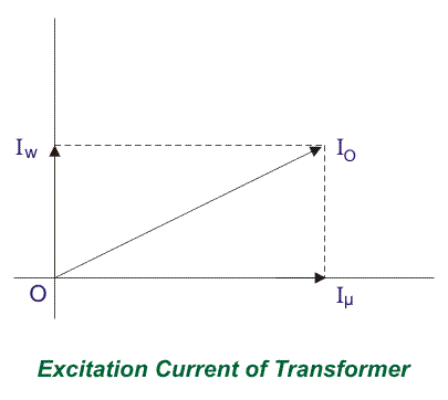
Because of this core loss component, the source current in a transformer on no-load condition supplied from the source as source current is not exactly at 90° lags of the supply voltage, but it lags behind an angle θ is less than 90o. If the total current supplied from source is Io, it will have one component in phase with supply voltage V1 and this component of the current Iw is the core loss component.

This component is taken in phase with the source voltage because it is associated with active or working losses in transformers. Another component of the source current is denoted as Iμ.

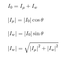
This component produces the alternating magnetic flux in the core, so it is watt-less; means it is a reactive part of the transformer source current. Hence Iμ will be in quadrature with V1 and in phase with alternating flux Φ. Hence, the total primary current in a transformer on the no-load condition can be represented as:

image.png

Now you have seen how simple it is to explain the theory of transformer in no-load.

image.png

Theory of Transformer on Load

Having No Winding Resistance and Leakage Reactance

image.png

Now we will examine the behavior of the above-said transformer on load, which means the load is connected to the secondary terminals. Consider, a transformer having core loss but no copper loss and leakage reactance. Whenever a load is connected to the secondary winding, the load current will start to flow through the load as well as the secondary winding.

This load current solely depends upon the characteristics of the load and also upon the secondary voltage of the transformer. This current is called secondary current or load current, here it is denoted as I2. As I2 is flowing through the secondary, a self MMF in secondary winding will be produced. Here it is N2I2, where, N2 is the number of turns of the secondary winding of the transformer.

image.png

This MMF or magnetomotive force in the secondary winding produces flux φ2. This φ2 will oppose the main magnetizing flux and momentarily weakens the main flux and tries to reduce primary self-induced emf E1. If E1 falls below the primary source voltage V1, there will be an extra current flowing from source to primary winding.

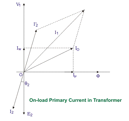
This extra primary current I2′ produces extra flux φ′ in the core which will neutralize the secondary counter flux φ2. Hence the main magnetizing flux of core, Φ remains unchanged irrespective of load. So total current, this transformer draws from the source can be divided into two components.

The first one is utilized for magnetizing the core and compensating the core loss, i.e., Io. It is the no-load component of the primary current. The second one is utilized for compensating the counter flux of the secondary winding. It is known as the load component of the primary current. Hence total no-load primary current I1 of an electrical power transformer having no winding resistance and leakage reactance can be represented as follows

Where θ2 is the angle between the Secondary Voltage and Secondary Current of the transformer.
Now we will proceed one further step toward a more practical aspect of a transformer.

Theory of Transformer On Load, with Resistive Winding, but No Leakage Reactance

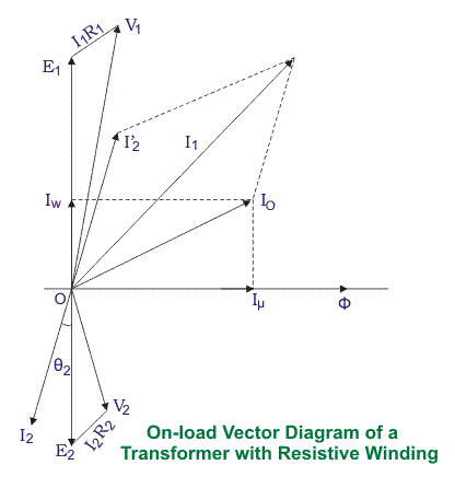
Now, consider the winding resistance of the transformer but no leakage reactance. So far we have discussed the transformer which has ideal windings, means winding with no resistance and leakage reactance, but now we will consider one transformer which has internal resistance in the winding but no leakage reactance. As the windings are resistive, there would be a voltage drop in the windings.

image.png

We have proved earlier that, total primary current from the source on load is I1. The voltage drop in the primary winding with resistance, R1 is R1I1. Obviously, induced emf across primary winding E1, is not exactly equal to source voltage V1. E1 is less than V1 by voltage drop I1R1.

image.png

Again in the case of secondary, the voltage induced across the secondary winding, E2 does not totally appear across the load since it also drops by an amount I2R2, where R2 is the secondary winding resistance and I2 is secondary current or load current.

Similarly, the voltage equation of the secondary side of the transformer will be:

image.png

Theory of Transformer On Load, with Resistance as well as Leakage Reactance

Now we will consider the condition when there is leakage reactance of the transformer as well as winding resistance of the transformer.

image.png

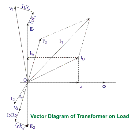
Let leakage reactances of primary and secondary windings of the transformer are X1 and X2 respectively. Hence total impedance of primary and secondary winding of transformer with resistance R1 and R2 respectively can be represented as,

image.png

We have already established the voltage equation of a transformer on load, with only resistances in the windings, where voltage drops in the windings occur only due to resistive voltage drop.

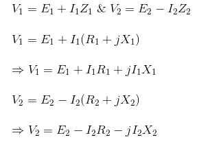
But when we consider leakage reactance of transformer windings, the voltage drop occurs in the winding not only due to resistance but also due to the impedance of transformer windings. Hence, the actual voltage equation of a transformer can easily be determined by replacing resistances R1 & R2 in the previously established voltage equations with Z1 and Z2.

Therefore, the voltage equations are,

image.png

Resistance drops are in the direction of the current vector. But a reactive drop will be perpendicular to the current vector as shown in the above vector diagram of the transformer.

Statement: Respect the original, good articles worth sharing, if there is infringement please contact delete.

Wenzhou Rockwell Transformer Co., Ltd. It is a high - tech enterprise integrating R & D, production, sales, and service. It focuses on the manufacturing of power transformers and supporting equipment, and is committed to providing efficient, reliable, and energy - saving power transmission and distribution solutions for global customers. We can offer: •Distribution transformers and substations •Outdoor switchgears and breakers(recloser) •Switchgears and it’s components (GIS, RMU, VCB, SF6 CB) Market and Service: We always take customers as the orientation and provide customized services according to their requirements. Our products are exported to the Middle East, Africa, Northern Europe, South America, and many other countries and regions. Drive the future of electricity with technological innovation and become a leading global supplier of intelligent power equipment.

Fault Analysis and Treatment of Oil-Immersed Transformers
Oil Leakage at Welded JointsOil leakage at welded joints primarily stems from poor welding quality, such as incomplete or detached welds, and defects like pinholes and gas pores. Although oil-immersed transformers are initially coated with solder and paint during manufacturing, potentially masking these issues temporarily, the defects tend to surface during operation. Additionally, electromagnetic vibration can cause weld cracks, leading to oil leakage.To resolve such leaks, the first critical s
08/29/2025
What losses occur during operation of the transformer? How to reduce losses?
Transformers experience various types of losses during operation, primarily categorized into two main types: copper losses and iron losses.Copper LossesCopper losses, also known as I²R losses, are caused by the electrical resistance of the transformer windings—typically made of copper. As current flows through the windings, energy is dissipated in the form of heat. These losses are proportional to the square of the load current (I²R), meaning they increase significantly with high
Rockwell
08/29/2025
Transformer Detection, Testing, Maintenance and Servicing
Transformer testing, inspection, and maintenance are essential tasks to ensure normal operation and extend the service life of transformers. Below are some recommended steps:Visual Inspection: Regularly inspect the transformer's exterior, including the enclosure, cooling system, and oil tank. Ensure the enclosure is intact, free from corrosion, damage, or leakage.Insulation Resistance Testing: Use an insulation resistance tester to check the transformer's insulation system. Verify that the insul
Vziman
08/29/2025
Preventive Detection and Testing of Transformers
I. DC Resistance Test of Transformer Primary and Secondary Windings:The DC resistance of transformer primary and secondary windings can be measured using the four-wire (Kelvin) method, which is based on principles related to accurate resistance measurement.In the four-wire method, two test leads are connected to both ends of the winding under test, while the other two leads are connected to adjacent winding terminals. An AC power source is then applied to the two leads connected to the adjacent
Rockwell
08/28/2025
Inquiry
Download
IEE-Business is dedicated to serving the personnel in the global power industry.
Join IEE-Business, not only can you discover power equipment and power knowledge, but also canhnd like - minded friends!