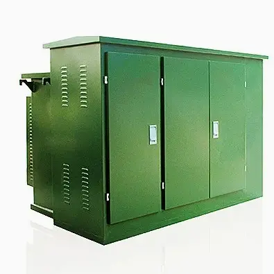
• Product
  • Suppliers
  • Manufacturers
  • Solutions
  • Free tools
  • Knowledges
  • Experts
  • Communities
Search


Comprehensive Analysis of Common Accessories of Dry-Type Transformers: From Enclosures to Copper Bars, Master Key Configurations in One Article

Rockwell
Field: Manufacturing
China

Enclosures

Enclosures can be categorized into indoor and outdoor types.

For indoor applications, considering heat dissipation and maintenance needs, it is generally recommended not to install an enclosure if there is sufficient installation space. However, if required by the user, enclosures with multiple observation holes can be provided. Enclosures can also be painted in colors preferred by the user.

The protection level of enclosures is typically IP20 or IP23:

  • IP20 prevents the ingress of solid foreign objects larger than 12 mm and protects against accidental impacts.

  • In addition to the functions of IP20, IP23 can prevent water droplets from entering within a 60-degree vertical angle, making it suitable for outdoor installation.

Enclosure materials include ordinary steel plates, injection-molded plastics, stainless steel plates, aluminum alloy composite plates, etc.

Enclosures.jpg

Temperature Controllers

All transformers are equipped with overheating protection devices. These devices detect and control the transformer temperature via PT thermistors built into the low-voltage windings, and output digital signals through an RS232/485 communication interface. The device provides the following functions:

  • During transformer operation, the temperature values of the three-phase windings are displayed on the circuit.

  • Displays the temperature value of the hottest-phase winding.

  • Over-temperature alarm and over-temperature shutdown.

  • Audible and visual alarms, and fan activation.

Temperature Controllers.jpg

Air-Cooling Devices

  • The cooling methods for dry-type transformers can be divided into natural air cooling (AN) and forced air cooling (AF).

  • Under natural air cooling (AN), the transformer can continuously supply 100% of its rated capacity under normal operating conditions.

  • Under forced air cooling (AF), a 50% capacity increase can be achieved under normal operating conditions, making it suitable for various emergency overloads or intermittent overload operations. Continuous overload operation using forced air cooling (AF) is generally not recommended, as it leads to greater increases in load losses and impedance resistance.

Air-Cooling Devices.jpg

Copper Bars

  • Generally, the cable inlet/outlet methods are classified into top inlet/outlet, bottom inlet/outlet, and side inlet/outlet.

  • For transformers with a rated power ≤ 200 kVA, the conventional outlet method is still used; side outlets are connected by the user via cables.

  • When the rated power is ≥ 1600 kVA:

  • Double-row feeders with a spacing of 10 (for 1600–2000 kVA) or 12 (for 2500 kVA) are used for phases A, B, and C.

  • Since the neutral line is located at the top of the transformer, if the neutral line needs to be led out from the bottom of the switchgear, it is recommended that the transformer’s neutral line still enters the switchgear from the top.

Give a tip and encourage the author!

Recommended

Impact of DC Bias in Transformers at Renewable Energy Stations Near UHVDC Grounding Electrodes
Impact of DC Bias in Transformers at Renewable Energy Stations Near UHVDC Grounding ElectrodesWhen the grounding electrode of an Ultra-High-Voltage Direct Current (UHVDC) transmission system is located close to a renewable energy power station, the return current flowing through the earth can cause a rise in ground potential around the electrode area. This ground potential rise leads to a shift in the neutral-point potential of nearby power transformers, inducing DC bias (or DC offset) in their
01/15/2026
Distribution Equipment Transformer Testing, Inspection, and Maintenance
1.Transformer Maintenance and Inspection Open the low-voltage (LV) circuit breaker of the transformer under maintenance, remove the control power fuse, and hang a “Do Not Close” warning sign on the switch handle. Open the high-voltage (HV) circuit breaker of the transformer under maintenance, close the grounding switch, fully discharge the transformer, lock the HV switchgear, and hang a “Do Not Close” warning sign on the switch handle. For dry-type transformer maintenance: first clean the porcel
12/25/2025
How to Test Insulation Resistance of Distribution Transformers
In practical work, insulation resistance of distribution transformers is generally measured twice: the insulation resistance between thehigh-voltage (HV) windingand thelow-voltage (LV) winding plus the transformer tank, and the insulation resistance between theLV windingand theHV winding plus the transformer tank.If both measurements yield acceptable values, it indicates that the insulation among the HV winding, LV winding, and transformer tank is qualified. If either measurement fails, pairwise
12/25/2025
Design Principles for Pole-Mounted Distribution Transformers
Design Principles for Pole-Mounted Distribution Transformers(1) Location and Layout PrinciplesPole-mounted transformer platforms should be located near the load center or close to critical loads, following the principle of “small capacity, multiple locations” to facilitate equipment replacement and maintenance. For residential power supply, three-phase transformers may be installed nearby based on current demand and future growth projections.(2) Capacity Selection for Three-Phase Pole-Mounted Tr
12/25/2025
Related Products
Send inquiry
+86
Click to upload file

IEE Business will not sell or share your personal information.

Download
Get the IEE Business Application
Use the IEE-Business app to find equipment, obtain solutions, connect with experts, and participate in industry collaboration anytime, anywhere—fully supporting the development of your power projects and business.