• Product
  • Suppliers
  • Manufacturers
  • Solutions
  • Free tools
  • Knowledges
  • Experts
  • Communities
Search


Transformer sa Pagkakataon na Nakalagay ng Load

Edwiin
Larangan: Pansakto ng kuryente
China

Pag-operasyon ng Transformer sa ilalim ng mga Kondisyon ng Load

Kapag ang isang transformer ay nasa ilalim ng load, ang kanyang secondary winding ay konektado sa isang load, na maaaring resistive, inductive, o capacitive. Ang isang current I2 ay lumilipad sa pamamagitan ng secondary winding, na may sukat na napagpasiyahan ng terminal voltage V2 at load impedance. Ang phase angle sa pagitan ng secondary current at voltage ay depende sa mga katangian ng load.

Paglalarawan ng Pag-operasyon ng Transformer sa ilalim ng Load

Ang pag-uugali ng operasyon ng isang transformer sa ilalim ng load ay detalyado bilang sumusunod:

Kapag ang secondary ng transformer ay open-circuited, ito ay humihingi ng no-load current mula sa pangunahing supply. Ang no-load current na ito ay nagpapakilos ng magnetomotive force N0I0, na nagtatatag ng flux Φ sa core ng transformer. Ang configuration ng circuit ng transformer sa ilalim ng kondisyon ng walang load ay ipinapakita sa diagrama sa ibaba:

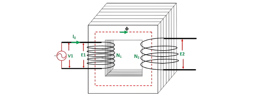
Interaksiyon ng Load Current ng Transformer

Kapag ang isang load ay konektado sa secondary ng transformer, ang current I2 ay lumilipad sa pamamagitan ng secondary winding, na nagpapakilos ng magnetomotive force (MMF) N2I2. Ang MMF na ito ay nagpapakilos ng flux ϕ2 sa core, na kontra sa orihinal na flux ϕ batay sa Lenz's law.

Difference ng Phase at Power Factor sa Transformer

Ang phase difference sa pagitan ng V1 at I1 ay nagtutukoy sa power factor angle ϕ1 sa primary side ng transformer. Ang secondary-side power factor ay depende sa uri ng load na konektado sa transformer:

  • Para sa inductive load (tulad ng ipinapakita sa phasor diagram sa itaas), ang power factor ay lagging.

  • Para sa capacitive load, ang power factor ay leading.

Ang kabuuang primary current I1 ay ang vector sum ng no-load current I0 at ang counter-balancing current I'1, i.e.,

Phasor Diagram ng Transformer na may Inductive Load

Ang phasor diagram ng aktwal na transformer sa ilalim ng inductive loading ay ipinapakita sa ibaba:

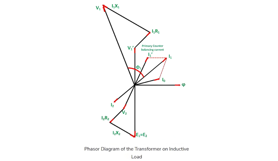
Mga Hakbang para Makonstruyi ang Phasor Diagram

  • Tumanggap ng flux Φ bilang reference.

  • Induced emfs E1 at E2 lag the flux by 90°.

  • Ang primary applied voltage component balancing E1 ay tinatawag na V'1 (i.e., V'1 = -E1).

  • No-load current I0 lags V'1 by 90°.

  • Para sa lagging power factor load, ang current I2 lags E2 by angle ϕ2.

  • Winding resistance and leakage reactance cause voltage drops, making the secondary terminal voltage:V2 = E2 −(voltage drops)

    • I2R2 is in phase with I2.

    • I2X2 is orthogonal to I2.

  • Primary current I1 is the phasor sum of I'1 and I0, where I'1 = -I2.

  • Primary applied voltage:V1 = V'1 + (primary voltage drops)

    • I1R1 is in phase with I1.

    • I1X1 is orthogonal to I1.

  • The phase difference between V1 and I1 defines the primary power factor angle ϕ1.

  • Secondary power factor:

    • Lagging for inductive loads (as in the phasor diagram).

    • Leading for capacitive loads.

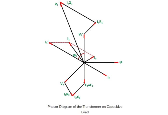
 Mga Hakbang para Gumuhit ng Phasor Diagram para sa Capacitive Load

  • Tumanggap ng flux Φ bilang reference.

  • Induced emfs E1 at E2 lag the flux by 90°.

  • The primary applied voltage component balancing E1 is denoted as V'1 (i.e., V'1 = -E1).

  • No-load current I0 lags V'1 by 90°.

  • For a leading power factor load, current I2 leads E2 by angle ϕ2.

  • Winding resistance and leakage reactance cause voltage drops, making the secondary terminal voltage:V2 = E2 −(voltage drops)

    • I2R2 is in phase with I2.

    • I2X2 is orthogonal to I2.

  • Counter-balancing current I'1 = -I2(equal in magnitude, opposite in phase to I2).

  • Primary current I1 is the phasor sum of I'1 and I0:

  • Primary applied voltage V1 is the phasor sum of V'1 and primary voltage drops:V1 = V'1 +(primary voltage drops)

    • I1R1 is in phase with I1.

    • I1X1is orthogonal to I1.

  • Power factor angles:

    • The phase difference between V1 and I1 defines the primary power factor angle ϕ1.

    • The secondary power factor (leading for capacitive loads) depends entirely on the connected load type.

Magbigay ng tip at hikayatin ang may-akda!
Inirerekomenda
Inquiry
I-download
Kumuha ng IEE-Business Application
Gamit ang app na IEE-Business upang makahanap ng kagamitan makuha ang mga solusyon makipag-ugnayan sa mga eksperto at sumama sa industriyal na pakikipagtulungan kahit kailan at saanman buong pagsuporta sa pag-unlad ng iyong mga proyekto at negosyo sa enerhiya