
Ang Synchronous Impedance Method, kasagaran gisulti usab ingon EMF Method, isipangita ang epekto sa armature reaction pinaagi sa equivalent imaginary reactance. Aron makalkula ang voltage regulation gamit kini nga paagi, kinahanglan kini mga data: resistance sa armature per phase, ang Open-Circuit Characteristic (OCC) curve nga nagpakita sa relasyon tali sa open-circuit voltage ug field current, ug ang Short-Circuit Characteristic (SCC) curve nga nagpakita sa relasyon tali sa short-circuit current ug field current.
Para sa synchronous generator, ang mga equation mahimong masulat isip:

Aron makalkula ang synchronous impedance Zs, gikuha ang mga sukat, ug ang value sa Ea (armature-induced EMF) adunay resulta. Gamiton ang Ea ug V (terminal voltage), komputar ang voltage regulation.
Pagsukat sa Synchronous Impedance
Determine ang synchronous impedance pinaagi sa tulo ka primary tests:
DC Resistance Test
Sa test na, ang alternator gitangtangan nga star-connected uban ang DC field winding open-circuited, sama sa circuit diagram sa dili pa:
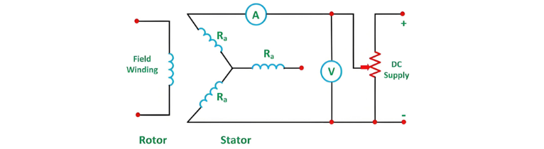
DC Resistance Test
Ang DC resistance tali sa bawhong pair of terminals gisukat pinaagi sa ammeter-voltmeter method o Wheatstone’s bridge. Ang average sa tulo ka measured resistance values Rt gikalkula, ug ang per-phase DC resistance RDC gideribahan pinaagi sa pagdivide sa Rt sa 2. Konsiderando ang skin effect, nga mobo-o sa effective AC resistance, ang per-phase AC resistance RAC gikinahanglan sa pagmultiply sa RDC sa factor nga 1.20–1.75 (typical value: 1.25), depende sa laki sa machine.
Open Circuit Test
Aron ma-determine ang synchronous impedance pinaagi sa open-circuit test, ang alternator mogamit sa rated synchronous speed uban ang load terminals open (loads disconnected) ug ang field current initially set to zero. Ang corresponding circuit diagram gihatagan sa dili pa:
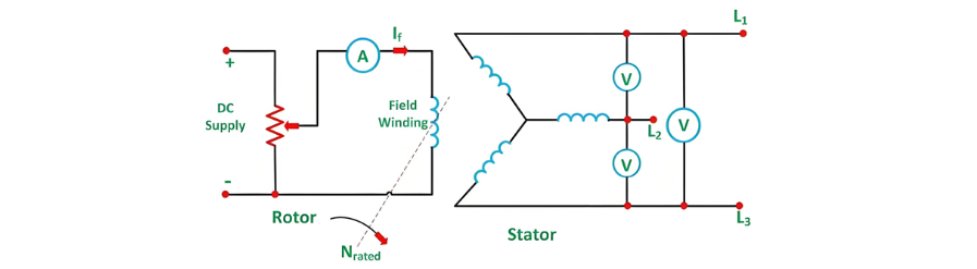
Open Circuit Test (Continued)
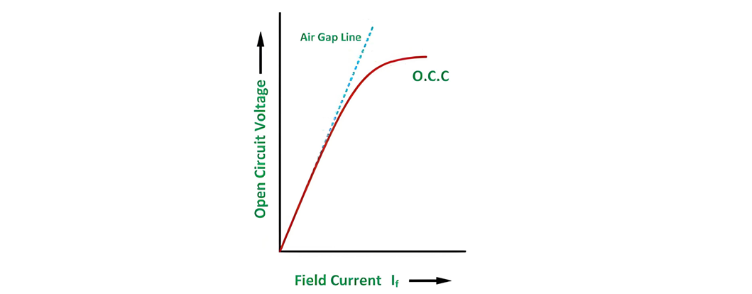
Pagkahuman sa pagset sa field current sa zero, gradual na mosugyot sa steps samantalang gisukat ang terminal voltage Et sa bawhong increment. Ang excitation current typical na moasenso hangtod ang terminal voltage mabuto sa 125% sa rated value. Gihimo ang graph tali sa open-circuit phase voltage Ep = Et/sqrt 3 ug ang field current If, yielding the Open Circuit Characteristic (O.C.C) curve. Kini nga curve mirroring ang shape sa standard magnetization curve, uban ang linear region extended aron magform og air gap line.
Ang O.C.C ug air gap line gihatagan sa figure sa dili pa:
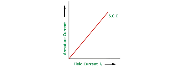
Short Circuit Test
Sa short circuit test, ang armature terminals gishort-circuited pinaagi sa tulo ka ammeters, sama sa figure sa dili pa:
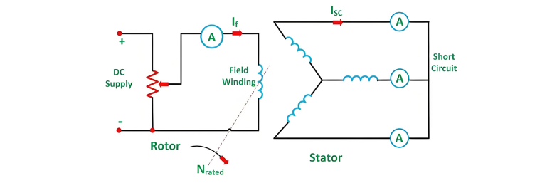
Short Circuit Test (Continued)
Bago mohuman ang alternator, ang field current gitubigan sa zero, ug ang bawhong ammeter gitakda sa range nga gibubo sa rated full-load current. Ang alternator mogamit sa synchronous speed, uban ang field current gradual na moasenso—similar sa open-circuit test—samantalang gisukat ang armature current sa bawhong increment. Ang field current adjusted hangtod ang armature current mabuto sa 150% sa rated value.
Sa bawhong step, ang field current If ug ang average sa tulo ka ammeter readings (armature current Ia) girecord. Ang graph plotting Ia against If yields the Short Circuit Characteristic (S.C.C), nga typical na forming a straight line, sama sa figure sa dili pa.
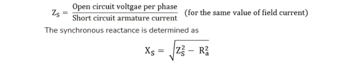
Calculation of Synchronous Impedance
Aron makalkula ang synchronous impedance Zs, unang overlay ang Open-Circuit Characteristic (OCC) ug Short-Circuit Characteristic (SCC) sa same graph. Sunod, determine ang short-circuit current ISC corresponding sa rated alternator voltage per phase Erated. Ang synchronous impedance derived as the ratio of the open-circuit voltage EOC (at the field current that yields Erated to the corresponding short-circuit current ISC, expressed as s = EOC / ISC.
Ang graph gihatagan sa dili pa:
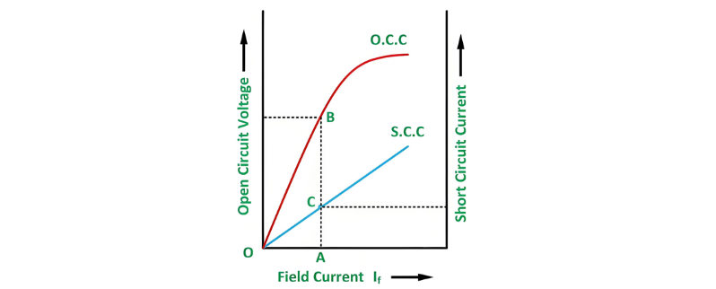
Gikan sa above figure, consider the field current If = OA, which produces the rated alternator voltage per phase. Corresponding to this field current, the open-circuit voltage is represented by AB.

Assumptions of the Synchronous Impedance Method
Ang synchronous impedance method assumes that synchronous impedance (determined from the ratio of open-circuit voltage to short-circuit current via OCC and SCC curves) remains constant when these characteristics are linear. It further assumes that flux under test conditions matches that under load, though this introduces error as short-circuited armature current lags voltage by ~90°, causing predominantly demagnetizing armature reaction. Armature reaction effects are modeled as a voltage drop proportional to armature current, combined with reactance voltage drop, with magnetic reluctance assumed constant (valid for cylindrical rotors due to uniform air gaps). At low excitations, is constant (linear/unsaturated impedance), but saturation reduces beyond the OCC's linear region (saturated impedance). This method yields higher voltage regulation than actual loading, earning it the term pessimistic method.


