A Novel Detection Method for Stuck Faults in Load Switches

In recent years, as distribution automation advances, load switches see wider use in distribution lines. Yet, mechanical - failure - induced accidents are on the rise, burdening line operation and maintenance.
Poor mechanical performance is the main cause of switch faults. Many scholars study large - scale switchgear operation, using methods like coil current detection, vibration signal analysis, switch travel testing, ultrasonic flaw detection, and infrared thermometry. Motor - current - based switch status detection works for circuit breakers and disconnectors but is less applied to load - switch drive - mechanism faults.
Research on field - running load switches shows energy - storage motor current signals reflect switch status. Mechanical issues (e.g., spring jamming, rust, gear jamming) in the drive mechanism alter current signal parameters (amplitude, duration, local peaks). Focusing on coastal areas’ common energy - storage motor rust - jamming, this paper studies fault feature extraction and identification. Steps: 1) Analyze motor current characteristics, split waveforms into 4 stages, and assess each stage. 2) Design a data - acquisition device for current waveforms under different conditions. 3) Propose a recording - start algorithm, feature extraction, and fault - identification methods. 4) Validate via experiments.
1 Energy - Storage Motor Current Characteristics Analysis
Load switches typically use DC motors to drive compression springs for energy storage. During motor operation, rotor - output torque and speed closely relate to stator - circuit current. The shunt - excited DC motor’s electromagnetic torque and voltage equations are as follows:

In Equation (1), T represents the electromagnetic torque; n represents the rotational speed; Ia represents the armature current; Ra represents the armature circuit resistance, which is a constant; Ea represents the winding induced electromotive force; U represents the terminal voltage; ΔU represents the contact voltage drop, which is a constant; ϕ represents the magnetic flux; Ce represents the electromotive force constant; and CT represents the torque coefficient. According to Equation (1), we can derive:

From Equation (2), when the load current is small, the armature reaction’s demagnetizing effect is negligible, so magnetic flux is considered constant, and electromagnetic torque is proportional to the load current. As the load current increases, torque rises but rotational speed tends to decrease. However, the demagnetizing effect from higher load current reduces magnetic flux, which would increase speed. These opposing effects typically cause a slight decrease in the shunt - excited motor’s speed.Figure 1 shows the typical current waveform of a DC energy - storage motor in operation, divided into 4 stages.
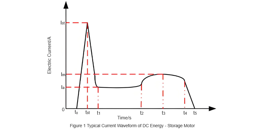
Stage 1 (t0)–(t1): Motor Start - up Stage
At time t0, the load switch receives a closing signal from the distribution terminal unit, energizing the control motor to start with load. The motor current surges to a start - up peak at (tst), then rapidly drops to enter stable operation.
Stage 2 (t1)–(t2): Motor Stable Operation Stage
The motor drives the transmission gear to idle. During this stage, the motor runs stably under light load, with the motor current amplitude at (Ia).
Stage 3 (t2)–(t4): Spring Energy - Storage Stage
As the compression spring stores energy, the motor’s output torque gradually increases, reaching a maximum at (t3); at this point, the motor current also hits the stage maximum (Im). Subsequently, the motor’s output torque gradually decreases.
Stage 4 (t4)–(t5): Motor Current Interruption Stage
At (t4), the compression spring reaches the limit switch, cutting off power to the motor. The motor current drops sharply until it reaches 0 at (t5), and the motor stops running.
2 Fault Diagnosis for Energy - Storage Motor Jamming
2.1 Fault Simulation & Data Acquisition
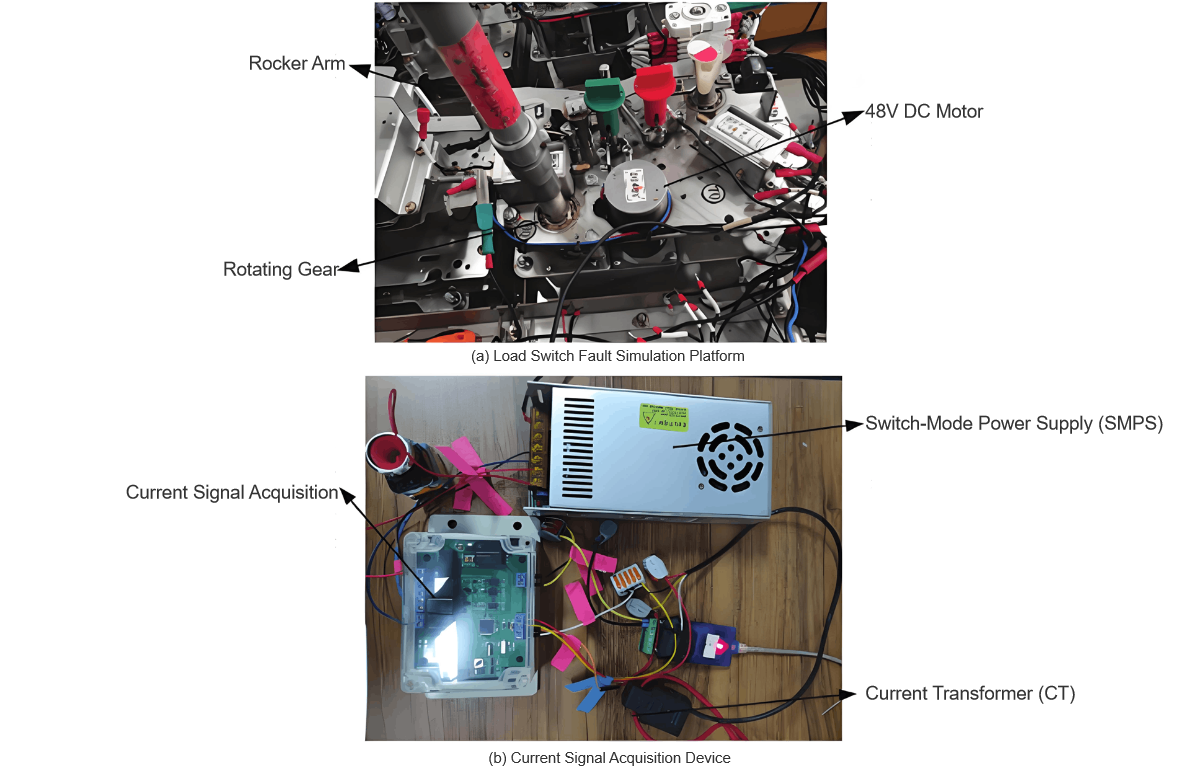
A jamming fault test was simulated on a load switch from an electrical equipment factory (scenario in Fig. 2(a)). After disassembling the switch, during the motor’s stable operation and spring energy - storage stages, a rocker applied reverse locked - rotor forces to simulate gear/spring jamming. A custom current acquisition device (Fig. 2(b)) used an ARM STM32F103 chip to collect signals from the HSTS016L Hall current transformer (DC input: 0–30A). Since the opening signal lacks the target current waveform, this study focuses on the closing current signal.
2.2 Waveform Recording Start Algorithm
From Figure 1, the effective signal waveform spans the time window t0 to t5, consisting of 4 stages with diverse current changes. Additionally, there are significant differences in signal amplitudes among different drive motors. Thus, using a simple current amplitude threshold as the start criterion for signal waveform recording is clearly inappropriate. Therefore, this study adopts the current change rate Kt within a unit time window and the mean value Imean as the start criteria to achieve effective waveform recording.Current change rate of the unit time window:

Mean current of each time window:

In Equations (3) and (4), Ii represents the current signal; M is the number of sampling points in the unit time window; Δ t is the time length of the unit time window, and Δ t = 0.02s in this paper; I(1) is the first sampling point in the unit time window.
2.3 Time - Domain Feature Extraction
To identify the jamming fault of the energy - storage motor, the expressive information of the curve is extracted through some time - domain indicators. The kurtosis K can characterize the smoothness of the current signal; the root mean square Irms can characterize the average energy of the current signal; the skewness sk is a measure of the direction and degree of skewness of the statistical data distribution; the form factor sh and the peak factor C are used to characterize the extreme degree of the current peak in the waveform.
The Random Forest (RF)classification algorithm integrates multiple decision trees. Its output category is determined by the mode of individual decision - tree categories, featuring high accuracy, good tolerance for abnormal data, and low overfitting risk.
2.4 Random Forest Algorithm
RF relies on Bootstrap sampling (with - replacement sampling to form n sample sets from the original dataset) and Bagging voting. Bagging generates n training sets via Bootstrap, each training an independent weak classifier. Final decisions come from voting on weak - classifier outputs, with the majority vote as the result.
RF uses CART decision trees (binary trees splitting top - down from the root, minimizing the Gini index for splits, formula (5)). Per Liu Min et al. 100 decision trees optimize classification performance. Thus, this study uses 100 CART trees for the random forest.

3 Case Analysis
3.1 Feature Selection
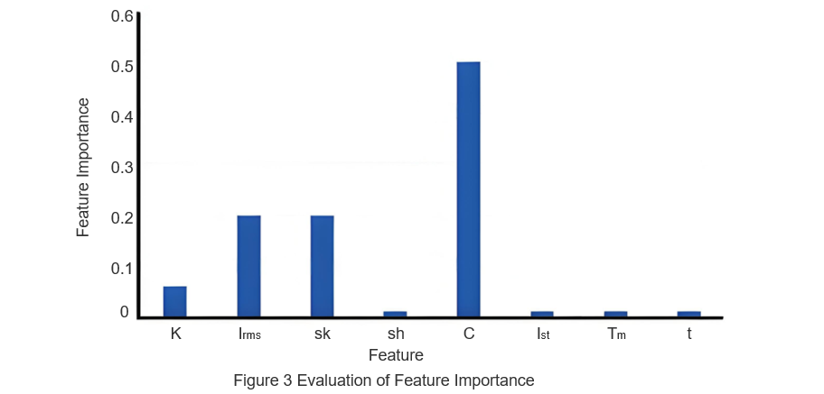
The Gini index in the random forest is used to evaluate the importance of each feature. The results are shown in Figure 3, where the ordinate represents the proportional coefficient. It can be seen that four feature quantities, namely the peak factor C, skewness sk, root mean square Irms, and kurtosis K, are highly important and can effectively characterize the differences in different states of the load switch. The four feature quantities, including the form factor sh, maximum starting current Ist, motor operating time t, and Tm, are of low importance. Therefore, this study selects C, sk, Irms, and K as the feature vectors.
3.2 Random Forest Diagnosis Results
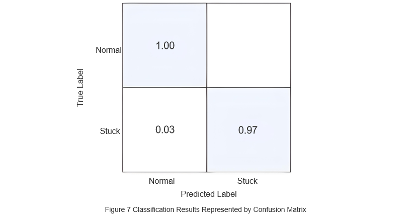
The RF algorithm classifies two load - switch states (normal/jammed) using 300 samples per state for training (total 600) and 30 samples for testing. The confusion matrix (Figure 4) shows perfect normal - state identification, 97% accuracy for jamming, and 98.33% average classification accuracy.
3.3 Comparison of Different Classification Algorithms
To test the performance of the random forest classifier, a Support Vector Machine (SVM) and an Extreme Learning Machine (ELM) are trained simultaneously for comparison. The test results are shown in Table 1.
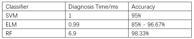
From Table 1, among the three classifiers, the Random Forest (RF) algorithm takes a relatively long diagnosis time of 6.9 ms for test set samples. In terms of accuracy, the Support Vector Machine (SVM) achieves 95% for two operating states, lower than RF. Due to random hidden - layer weights, the Extreme Learning Machine (ELM) has accuracy fluctuating between 85% - 96.67% and poorer robustness than RF. Thus, the RF algorithm used has high accuracy and good robustness.
4 Conclusion
This paper proposes a load - switch mechanical fault detection method using energy - storage motor current time - domain features and the Random Forest (RF) algorithm. It extracts representative time - domain features from motor current waveforms and uses an RF classifier for state identification. The proposed recording - wave start criterion effectively acquires motor current signals. Leveraging the Gini index in RF, it evaluates feature importance and selects four key features (peak factor, skewness, root mean square, kurtosis) to characterize load - switch states. Experiments show the method effectively identifies motor jamming states with 98.33% accuracy.