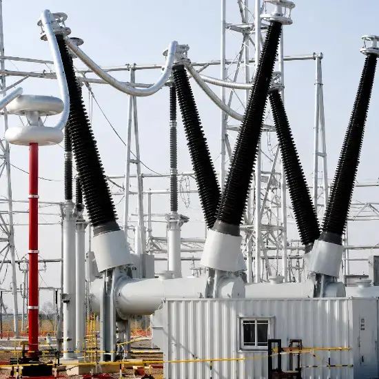
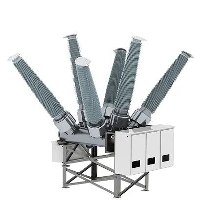
In the field of high-voltage engineering, the distinction between Live Tank and Dead Tank circuit breakers represents two fundamentally different design philosophies. As an expert in power systems, I will provide a deep technical analysis of these two types, focusing on their structural mechanics, insulation physics, and practical engineering applications.
1. Conceptual Origins: The "Tank"
The term "Tank" refers to the metal enclosure that houses the Interrupter (the component responsible for extinguishing the arc).
- Live Tank Breaker: The interrupter is mounted on top of a support insulator. In the closed position, the metal tank housing the interrupter is at the same potential as the system voltage. It is "Live."
- Dead Tank Breaker: The interrupter is placed inside a metal enclosure that is solidly grounded. The tank is "Dead." High-voltage current is brought into and out of the tank through specialized Bushings.
2. Structural Comparison & Diagrams
To understand the spatial logic of these designs, let’s examine the side-by-side structural layouts.
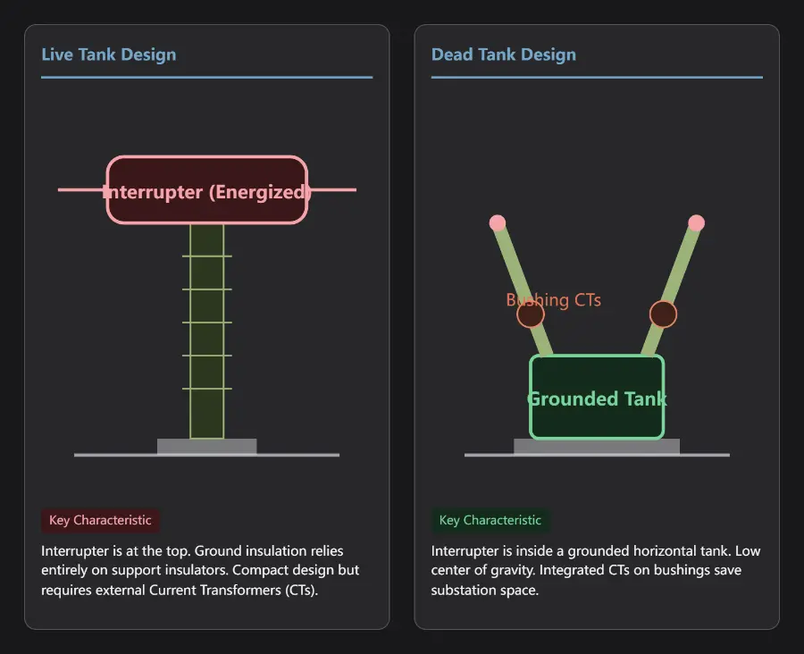
3. Deep Dive into Technical Differences
A. Insulation Mechanism and Electric Field
- Live Tank: Ground insulation depends entirely on external porcelain or composite support insulators. Inside the interrupter chamber, insulation is only needed between the open contacts. The external environment requires significant air clearance to prevent flashovers to the ground.
- Dead Tank: Insulation is shared between SF6 gas and solid insulators. The energized contacts and the grounded enclosure are separated by high-pressure SF6 gas. Since the tank is grounded, the electric field is concentrated in the radial gap between the contacts and the tank wall, allowing for a much more compact internal design.
B. Current Transformer (CT) Integration
This is the most critical engineering distinction:
- Live Tank: Because the tank is energized, CTs cannot be mounted directly on it. Independent, stand-alone electromagnetic CTs must be installed within the bay. This increases the number of civil foundations and the total substation footprint.
- Dead Tank: The bushings serve as ready-made primary conductors. By installing ring-type CTs (Bushing CTs) at the base of the bushings, 6 to 12 sets of CT windings can be easily accommodated within one breaker bay. This is highly advantageous for EHV/UHV systems requiring multiple protection redundancies (e.g., busbar, line, and breaker failure protection).
C. Mechanical Stability and Seismic Performance
In physics terms, a Live Tank breaker is "top-heavy." For 550kV systems, the interrupter and support insulators can reach heights of 7–10 meters. In seismic zones, the bending moments at the base of the porcelain insulators are massive, leading to a high risk of fracture. The Dead Tank breaker has an extremely low center of gravity, effectively sitting on the ground. This gives it a natural seismic advantage, making it the standard choice in earthquake-prone regions like Japan and the West Coast of the US.
4. Technical Data Comparison Table
Below are typical parameters for a 252kV / 3150A / 50kA circuit breaker:
| Parameter |
Live Tank Breaker |
Dead Tank Breaker |
| Footprint per phase |
~1.2 m² |
~4.5 m² (Integrated) |
| Total Height |
7,500 mm - 8,500 mm |
4,500 mm - 5,500 mm |
| Center of Gravity (CG) |
High (~4,000 mm) |
Low (~1,500 mm) |
| Weight per phase |
~1,500 kg |
~6,000 kg (Includes CTs) |
| SF6 Gas Volume |
~15 kg/phase |
~80 kg/phase (Large tank) |
| Current Transformers |
External standalone CTs required |
Integrated Bushing CTs (up to 12) |
| Seismic Rating |
0.2g - 0.3g (Requires dampers) |
0.5g - 1.0g (Excellent) |
| Installation Time |
Short (Modular) |
Longer (Gas processing & CT wiring) |
5. Selection Logic: Regional Preferences
- IEC / China (Live Tank Bias): In IEC-standardized markets, Live Tank breakers are often preferred for their cost efficiency. They use significantly less SF6 gas and offer better flexibility for CT replacement. In UHV (800kV+) applications, multi-break Live Tank units are easier to manufacture than massive grounded tanks.
- ANSI / North America (Dead Tank Bias): Dead Tank breakers are the standard here. Despite being larger as a single unit, they reduce the total bay length by eliminating separate CT foundations. The integrated nature of the CTs also protects them from environmental pollution.
6. Expert Perspective on Maintenance
While Dead Tank breakers offer integrated convenience, they present higher gas leakage management risks. The sealing perimeter (O-rings) of a Dead Tank is much larger. Furthermore, a failure in a Bushing CT can contaminate the entire SF6 gas volume within the tank, leading to internal flashovers and significantly higher repair costs compared to replacing a standalone CT in a Live Tank setup.
Additionally, with increasing environmental regulations, the massive SF6 charge in Dead Tank breakers is under scrutiny. The industry is currently moving towards Vacuum-Interrupter Dead Tank designs or using alternative gases (like g3 or C4-FN) to reduce the carbon footprint.
Summary
The choice between Live Tank and Dead Tank is a trade-off between "Lightweight Flexibility" and "High-Integrity Stability."
- Choose Live Tank if you are in a non-seismic inland area and prioritize lower SF6 costs and flexible CT maintenance.
- Choose Dead Tank if you are in a seismic zone or a space-constrained substation that requires maximum integration and protection against harsh environmental conditions.
Contact us:
Edited From:Dyson

 Login