What is a Grounding Transformer?
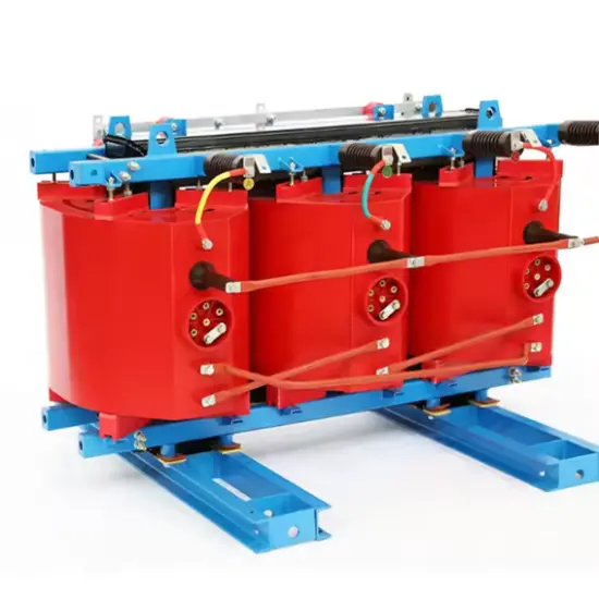
A grounding transformer, abbreviated as "grounding transformer," can be classified into oil-immersed and dry-type according to the filling medium; and into three-phase and single-phase grounding transformers according to the number of phases.
Difference Between Grounding Transformers and Conventional Transformers
The purpose of a grounding transformer is to create an artificial neutral point for connecting an arc suppression coil or resistor when the system is connected in delta (Δ) or wye (Y) configuration without an accessible neutral point. Such transformers use zigzag (or "Z-type") winding connections. The key difference from conventional transformers is that each phase winding is split into two groups wound in opposite directions on the same magnetic core limb. This design allows zero-sequence magnetic flux to flow through the core limbs, whereas in conventional transformers, zero-sequence flux travels along leakage paths.
Therefore, the zero-sequence impedance of a Z-type grounding transformer is very low (around 10 Ω), while that of a conventional transformer is much higher. According to technical regulations, when using a conventional transformer to connect an arc suppression coil, the coil capacity must not exceed 20% of the transformer’s rated capacity. In contrast, a Z-type transformer can carry an arc suppression coil at 90%–100% of its own capacity. Additionally, grounding transformers can supply secondary loads and serve as station service transformers, thereby saving investment costs.
Working Principle of Grounding Transformers
A grounding transformer artificially creates a neutral point with a grounding resistor, which typically has a very low resistance (generally required to be less than 5 ohms). Moreover, due to its electromagnetic characteristics, the grounding transformer presents high impedance to positive- and negative-sequence currents, allowing only a small excitation current to flow in the windings. On each core limb, the two winding sections are wound in opposite directions. When equal zero-sequence currents flow through these windings on the same limb, they exhibit low impedance, resulting in minimal voltage drop.
During a ground fault, the windings carry positive-, negative-, and zero-sequence currents. The winding presents high impedance to positive- and negative-sequence currents, but low impedance to zero-sequence current because, within the same phase, the two windings are connected in series with opposite polarity—their induced electromotive forces are equal in magnitude but opposite in direction, thus canceling each other out.
Many grounding transformers are used solely to provide a low-resistance neutral point and do not supply any secondary load; therefore, many are designed without a secondary winding. During normal grid operation, the grounding transformer operates essentially in a no-load state. However, during a fault, it carries fault current only for a short duration. In a low-resistance grounded system, when a single-phase ground fault occurs, highly sensitive zero-sequence protection quickly identifies and temporarily isolates the faulty feeder.
The grounding transformer is active only during the brief interval between fault occurrence and the operation of the feeder’s zero-sequence protection. During this time, zero-sequence current flows through the neutral grounding resistor and the grounding transformer, following the formula: IR = U / R₁, where U is the system phase voltage and R₁ is the neutral grounding resistance.

Consequences When the Grounding Arc Cannot Be Reliably Extinguished
Intermittent extinction and reignition of the single-phase ground arc generates arc-ground overvoltages with amplitudes reaching up to 4U (where U is the peak phase voltage) or even higher, lasting for extended durations. This poses severe threats to the insulation of electrical equipment, potentially causing breakdowns at weak insulation points and leading to significant losses.
Sustained arcing ionizes the surrounding air, degrading its insulating properties and increasing the likelihood of phase-to-phase short circuits.
Ferroresonant overvoltages may occur, easily damaging voltage transformers and surge arresters—potentially even causing arrester explosions. These consequences severely endanger the insulation integrity of grid equipment and threaten the safe operation of the entire power system.
What Are Positive-, Negative-, and Zero-Sequence Currents?
Negative-sequence current: Phase A lags Phase B by 120°, Phase B lags Phase C by 120°, and Phase C lags Phase A by 120°.
Positive-sequence current: Phase A leads Phase B by 120°, Phase B leads Phase C by 120°, and Phase C leads Phase A by 120°.
Zero-sequence current: All three phases (A, B, C) are in phase—no phase leads or lags another.
During three-phase short-circuit faults and normal operation, the system contains only positive-sequence components.
During single-phase ground faults, the system contains positive-, negative-, and zero-sequence components.
During two-phase short-circuit faults, the system contains positive- and negative-sequence components.
During two-phase-to-ground short-circuit faults, the system contains positive-, negative-, and zero-sequence components.
Operating Characteristics of Grounding Transformers
The grounding transformer operates under no-load conditions during normal grid operation and experiences short-term overload during faults. In summary, the function of a grounding transformer is to artificially create a neutral point for connecting a grounding resistor. During a ground fault, it exhibits high impedance to positive- and negative-sequence currents but low impedance to zero-sequence current, ensuring reliable operation of ground-fault protection.
Neutral Grounding via Arc Suppression Coil Systems
When a transient single-phase ground fault occurs in the grid due to poor equipment insulation, external damage, operator error, internal overvoltage, or any other cause, the ground fault current flows through the arc suppression coil as inductive current, which is opposite in direction to the capacitive current. This can reduce the current at the fault point to a very small value or even zero, thereby extinguishing the arc and eliminating associated hazards. The fault clears automatically without triggering relay protection or circuit breaker tripping, significantly improving power supply reliability.
Three Compensation Operating Modes
There are three different compensation operating modes: under-compensation, full compensation, and over-compensation.
Under-compensation: The inductive current after compensation is less than the capacitive current.
Over-compensation: The inductive current after compensation is greater than the capacitive current.
Full compensation: The inductive current after compensation equals the capacitive current.
Compensation Mode Used in Neutral Grounding via Arc Suppression Coil Systems
In systems with neutral grounding through an arc suppression coil, full compensation must be avoided. Regardless of the magnitude of system unbalance voltage, full compensation can cause series resonance, subjecting the arc suppression coil to dangerously high voltages. Therefore, over-compensation or under-compensation is adopted in practice, with over-compensation being the most commonly used mode.
Main Reasons for Adopting Over-Compensation
In under-compensated systems, high overvoltages can easily occur during faults. For example, if part of the lines is disconnected due to a fault or other reasons, an under-compensated system may shift toward full compensation, causing series resonance and resulting in very high neutral displacement voltage and overvoltage. Large neutral displacement in under-compensated systems also threatens insulation integrity—a drawback that cannot be avoided as long as under-compensation is used.
During normal operation of an under-compensated system with significant three-phase imbalance, very high ferroresonant overvoltages may occur. This phenomenon arises from ferromagnetic resonance between the under-compensated arc suppression coil (where ωL > 1/(3ωC₀)) and the line capacitance (3C₀). Such resonance does not occur with over-compensation.
Power systems continuously expand, and the grid’s capacitance to ground increases accordingly. With over-compensation, the originally installed arc suppression coil can remain in service for some time—even if it eventually shifts toward under-compensation. However, if the system starts with under-compensation, any expansion immediately requires additional compensation capacity.
With over-compensation, the current flowing through the fault point is inductive. After arc extinction, the recovery rate of the faulted phase voltage is slower, making arc re-ignition less likely.
Under over-compensation, a decrease in system frequency only temporarily increases the degree of over-compensation, which poses no issue during normal operation. Conversely, under-compensation combined with reduced frequency may bring the system close to full compensation, leading to increased neutral displacement voltage.
Summary
The grounding transformer also functions as a station service transformer, stepping down 35 kV voltage to 380 V low voltage to supply power for battery charging, SVG fan power, maintenance lighting, and general station auxiliary loads.
In modern power grids, cables are widely replacing overhead lines. Since the single-phase capacitive ground-fault current of cable lines is much larger than that of overhead lines, neutral grounding via arc suppression coils often fails to extinguish the fault arc and suppress dangerous resonant overvoltages. Therefore, our substation adopts a low-resistance neutral grounding scheme. This approach is similar to solidly grounded neutral systems and requires installation of single-phase ground-fault protection that operates to trip breakers. Upon occurrence of a single-phase ground fault, the faulty feeder is rapidly isolated.