| Brand | ROCKWILL |
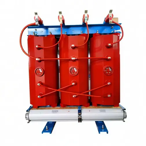
| Model NO. | 6kV 6.3kV 6.6kV 10kV 10.5kV 11kV Neutral Grounding/earthing Transformer Dry Type Power Transformer direct supply |
| Rated voltage | 11kV |
| Rated frequency | 50/60Hz |
| Rated capacity | 630kVA |
| Series | DKSC |
Description
As the trailblazer and China’s first dedicated original manufacturer in the earthing transformer domain, decades of intensive technical expertise accumulation have furnished us with formidable strength and even established the primitive standards for industrial development. From pioneering breakthroughs in core technology R&D to large-scale mass production and delivery, we have constructed a full-chain independent ecosystem. Leveraging leading and stable product performance along with ultra-reliable quality, we have emerged as a trusted preferred choice in the power grid construction sector.
6kV 6.3kV 6.6kV 10kV 10.5kV 11kV Neutral Grounding/earthing Transformer Dry Type Power Transformer with epoxy resin casting offer excellent insulation, fireproof and moisture-proof capabilities. By establishing neutral points, they efficiently connect arc suppression coils or grounding resistors to quickly suppress grid grounding fault currents, enhancing power supply reliability. Suitable for 10kV/35kV distribution networks, data centers, commercial buildings, etc.
Product Advantages:
Designed to excel in demanding power distribution scenarios, our transformers integrate cutting-edge technology to deliver unmatched reliability and performance.
Main technical specifications
The following table details the key technical specifications of the product, comprehensively covering electrical performance, mechanical characteristics, and dimensional parameters to provide a clear reference for technical selection and application scenarios.
Number of phases |
Three |
Input voltage |
10kV 11kV 22KV 33kV 34.5kV 35kV |
frequency |
50Hz, 60Hz |
use |
power transformer |
application |
Power transformers |
Product name |
Epoxy cast dry -type transformer |
material |
100% copper |
Cooling method |
Free air cooling/AF |
Output voltage |
440V, 460V, 230V |
Number of coils |
Three Windings |
Coil structure |
round coil |
type |
Dry |
frequency |
50Hz |
authentication |
ISO CCC IEC |
customize |
accept |
Rated capacity (kVA) |
Voltage combination (kV) |
Connect the group symbol |
No-load loss (W) |
Load loss of heat resistance class under different insulation (W) |
No-load current % |
||||
H.V. |
High Voltage Taps % |
Length |
130℃(B)(100℃) |
155℃(B)(120℃) |
180℃(B)(145℃) |
||||
30 |
6 6.3 6.6 10 10.5 11 |
±5 ±2×2.5 |
0.4 |
Yyno Dyn11 |
130 |
605 |
640 |
685 |
4.0 |
50 |
185 |
845 |
900 |
965 |
|||||
80 |
250 |
1160 |
1240 |
1330 |
|||||
100 |
270 |
1330 |
1415 |
1520 |
|||||
125 |
320 |
1565 |
1665 |
1780 |
|||||
160 |
365 |
1800 |
1915 |
2050 |
|||||
200 |
420 |
2135 |
2275 |
2440 |
|||||
250 |
490 |
2330 |
2485 |
2665 |
|||||
315 |
600 |
2945 |
3125 |
3355 |
|||||
400 |
665 |
3375 |
3590 |
3850 |
|||||
500 |
790 |
4130 |
4390 |
4750 |
|||||
630 |
910 |
4975 |
5290 |
5660 |
|||||
630 |
885 |
5095 |
5365 |
5760 |
6.0 |
||||
800 |
1035 |
5830 |
6265 |
6715 |
|||||
1000 |
1205 |
6885 |
7315 |
7885 |
|||||
1250 |
1420 |
8190 |
8720 |
9335 |
|||||
1600 |
1665 |
9945 |
10555 |
11320 |
|||||
2000 |
2075 |
12240 |
13005 |
14005 |
|||||
2500 |
2450 |
14535 |
15445 |
16605 |
|||||
Usage Conditions
Grounding System Compatibility
Suitable for ungrounded or low-current grounded neutral systems, and can be used in conjunction with resistor cabinets and arc suppression coils.
Electrical Environment Requirements
Grid frequency: 50/60 Hz; short-time withstand current: ≤25 kA; continuous ground fault operation time: ≥2 hours.
Installation Environment Conditions
Ambient temperature: -5°C to +40°C

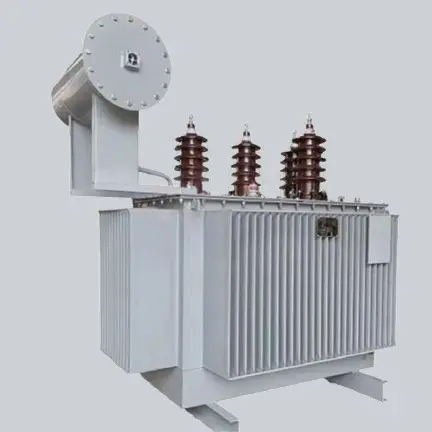

Upon arrival, the first step is visual inspection for tank deformation, paint damage, oil leakage on welds, flanges and valve connections.
The nameplate data should be cross-checked against the technical datasheet, including winding material, rated neutral current, zero-sequence impedance tolerance, auxiliary winding voltage and cooling method.
The oil level gauge reading and sealing status need confirmation. Before energization, routine field tests are recommended: winding resistance, vector group verification, insulation resistance and dielectric loss measurement.
If it is equipped with an auxiliary winding, no-load voltage test should be carried out to verify the low-voltage output. All factory test certificates shall be kept for local grid inspection and audit.
Professional power engineering support is available throughout the whole project cycle. Before energization, engineers can provide remote guidance for pre-commissioning inspection, wiring check and protection coordination confirmation. For on-site faults or abnormal alarms, technical support channels are accessible round the clock for emergency grid-related issues.
Remote diagnosis via photos, test reports and operation data is prioritized for fast troubleshooting. If remote analysis cannot resolve the issue, a tailored on-site service schedule will be arranged according to project priority and regional logistics.
Customized technical training for operation and maintenance teams is available, either held at the factory workshop or conducted remotely online.
Training modules include product structure introduction, working principle of zigzag earthing transformers, routine inspection checklist, permitted and forbidden operating actions, interpretation of nameplate and test reports, fault symptom identification, basic troubleshooting steps, as well as safety precautions during maintenance.
After training, operation staff will be able to carry out daily patrols, record operating data and judge common abnormal conditions independently. Training materials including operation manuals and PPT documents will be supplied for internal archive.
Core spare parts can be supplied long-term after project handover. The drawing library and component BOM will be archived for many years to guarantee matching replacement parts, such as temperature controllers, cooling fans, temperature sensors, terminal insulators and protective accessories.
Even after the standard warranty expires, spare parts can be supplied at reasonable commercial prices. It is recommended to prepare a spare parts list together during the tender stage, stocking critical wearing components on site to shorten response time when faults occur.
A complete document package will be delivered along with the equipment. It includes factory test reports, type test certificates, nameplate datasheet, operation & maintenance manual, dimensional drawing, foundation drawing, wiring diagram, quality certificate and material traceability documents.
All documents follow IEC requirements and can be directly submitted for grid inspection, project acceptance and archive. If the local power company has special document formats or additional test requirements, the documentation can be adjusted before shipment.
AF means forced air cooling with fans, while natural air cooling relies only on air convection around the cast coils. With fans running, heat is removed from the resin winding surface faster, so the transformer can carry higher load or fault current within the allowed temperature rise limit.
When fans fail, the unit must operate at a reduced capacity under natural cooling rules. Cooling selection should consider ambient temperature, enclosure ventilation and the fault duty. If installed inside sealed cabinet rooms with poor airflow, forced air cooling is commonly selected to avoid excessive temperature rise and premature thermal ageing of the epoxy insulation.
Round coils distribute electric field more evenly across the insulation surface compared with rectangular coils. There are no sharp corners where electric field concentrates, which helps maintain low partial discharge performance and improves lightning impulse withstand capacity.
During epoxy pouring, round winding geometry also supports better resin flow and bubble elimination inside the mould, reducing casting voids that are common failure points in resin transformers. Round coils also show better mechanical strength when impacted by high short‑circuit forces during earth faults, resisting winding deformation and displacement.
Multiple insulation thermal classes can be configured, corresponding to different maximum allowable hot‑spot temperatures and temperature rise limits. Lower temperature rise puts less thermal stress on the epoxy resin and copper conductors, slowing thermal ageing and extending expected service life.
For installations with high ambient temperature or frequent fault cycling, a higher thermal class with lower temperature rise margin is recommended. Temperature rise data is verified during factory type tests, and the thermal class selection must be coordinated with enclosure design, cooling method and site ambient conditions.
Overrunning beyond temperature rise limits will cause irreversible degradation of epoxy insulation.
Standard cast resin dry‑type transformers are primarily designed for indoor use. Even though the resin has good moisture resistance, outdoor exposure brings combined risks of direct sunlight, heavy rain, dew cycling, bird contamination and strong ultraviolet radiation. UV rays will gradually degrade epoxy resin surface, causing chalking and surface tracking over time.
For outdoor deployment, an IP‑rated protective metal enclosure with UV‑resistant coating, rain shelter and proper ventilation must be provided. Special outdoor anti‑UV resin formulation can also be specified at the design stage to improve weathering resistance.











 Login