Study on Optimal Resistance Selection of Resistive Superconducting Fault Current Limiters for Flexible DC Transmission Systems

1 Resistive Superconducting Fault Current Limiter
1.1 Operating Principle
As power grid scales continue to expand, the short-circuit capacity of domestic power systems is rapidly increasing, posing significant challenges to grid construction and operation. To address the problem of excessive short-circuit currents, superconducting fault current limiters (SFCLs) based on superconductivity principles are receiving growing attention. Depending on their damping characteristics when transitioning into the high-resistance state, SFCLs can be classified into resistive and inductive types.
Among these, the resistive superconducting fault current limiter features a simple structure, compact size, and light weight, with a clear operating principle. Once it enters the high-resistance state, its current-limiting impedance increases sharply, providing strong fault current suppression capability. Moreover, the device capacity can be flexibly adjusted through series or parallel configurations of superconductors. In recent years, breakthroughs in room-temperature superconducting materials have emerged, leading both academia and industry to widely regard resistive SFCLs as the primary direction for future development.
Critical current, critical magnetic field, and critical temperature are key physical parameters for determining whether a superconductor is in the superconducting state. When any of these parameters exceeds its critical value, the superconductor transitions from the superconducting state to the quenched state. The quenching process consists of two stages: first, the flux flow state, followed by the normal resistive state. When the current density through the superconductor exceeds its critical current density, the superconductor enters the flux flow state.
Where: E is the electric field strength; EC is the critical electric field strength; J is the current density; JCT is the critical current density; α is a constant; Tt1 and Tt2 are the temperatures of the superconductor at times t1 and t2, respectively; QRS is the heat generated by resistance Rs from t1 to t2; QC is the heat exchanged between the superconductor and its surrounding environment during the time interval t1–t2; Cm is the specific heat capacity of the superconductor; JCT(77) is the critical current density at 77 K (77 K being the temperature of a liquid nitrogen environment); TC is the critical temperature; T is the temperature of the superconductor.
According to Eq. (1), when the current density J increases, the electric field strength E of the superconductor rises rapidly, leading to an increase in its resistance. The increased resistance enhances the thermal effect, and as shown in Eq. (2), the superconductor's temperature rises accordingly.
From Eq. (3), it is known that the rise in temperature reduces the critical current density, further increasing the electric field strength E, causing the superconductor's resistance to grow continuously. As the resistance increases, the heat generated by the superconductor gradually balances with the heat dissipated to the surroundings, and the temperature stabilizes, eventually reaching a constant-resistance normal state.
1.2 Application of R-SFCL in Flexible DC Systems
In flexible DC transmission systems, DC current lacks natural zero-crossings. Once a short-circuit fault occurs, the fault current rises rapidly, posing a severe threat to electrical equipment in the system. To ensure system reliability, circuit breakers must quickly isolate the faulted line. Currently, DC circuit breakers have not yet fully met practical application requirements.
When a DC-side fault occurs, AC-side breakers are typically tripped, but this inevitably causes the converter station to shut down, and power electronic devices may be damaged due to overcurrent during this period. DC protection must complete the entire protection sequence within a few milliseconds, whereas the fastest operating time of AC circuit breakers is typically 50 ms, making them unable to effectively protect power electronic devices in the system.
Current technology enables R-SFCLs to reach the normal resistive state within approximately 3 ms. The resistive superconducting fault current limiter transitions into the current-limiting state much faster than relay protection operates, and achieves the high-impedance state before fault clearance, thereby effectively reducing the short-circuit current.
2 DC Fault Characteristics in Flexible DC Systems
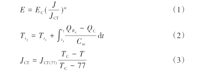
The location of the fault point affects only the system impedance, not the current path or the fundamental characteristics of the short-circuit fault. For modeling convenience, the fault is placed at the midpoint of the DC line and assumed to be a metallic short circuit. A two-terminal flexible DC system simulation model and an R-SFCL model are built using PSCAD/EMTDC, with a system rated voltage of ±110 kV and a rated power of 75 MW. The installation location of the R-SFCL is shown in Fig. 1.
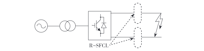
When a DC short-circuit fault occurs, the IGBT is detected and immediately blocked via its blocking function upon sensing the fault current. However, the diodes connected in parallel with the IGBT and the transmission lines form an uncontrollable bridge rectifier circuit, allowing commutation to continue even after the IGBT is blocked. A DC pole-to-pole short circuit can be mainly divided into three stages: The first stage occurs immediately after the fault, during which the DC-side capacitor discharges rapidly and the DC current rises to its peak value within a few milliseconds.
In the second stage, after the capacitor voltage drops to zero, the current flowing through the diodes can reach more than ten times their rated current, making power electronic devices highly susceptible to damage. In the third stage, when the DC short-circuit current decays below the AC grid current, the AC grid begins feeding short-circuit current into the DC fault point. A DC ground fault does not have a second stage; otherwise, its characteristics are similar to those of a pole-to-pole fault.
During AC current feed-in, the fault current through the diodes is approximately ten times their rated current. The current paths for these two types of DC short-circuit faults in the flexible DC system are illustrated in Fig. 2 and Fig. 3, respectively. Installing an R-SFCL along the fault current path can rapidly increase the resistance of the short-circuit loop, providing more time for fault clearance and reducing the requirements on the inherent opening time and interrupting capacity of DC circuit breakers.
3 Simulation Analysis
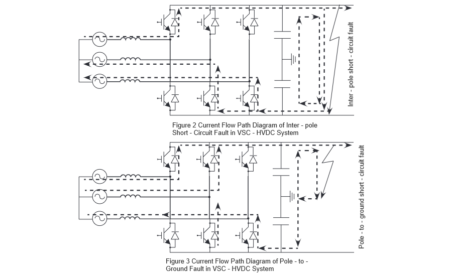
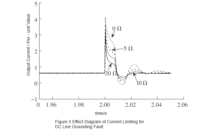
Using the PSCAD/EMTDC simulation software, the developed R-SFCL model is integrated into the established two-terminal flexible DC system simulation model with a capacity of 75 MW for verification. The current-limiting performance under DC pole-to-pole fault is shown in Fig. 4, and that under DC line-to-ground fault is shown in Fig. 5. As can be seen from Fig. 4 and Fig. 5, the peak fault current decreases as the normal-state resistance increases. It is evident that the resistance of the R-SFCL and the peak fault current after installation exhibit a certain decaying functional relationship.
To broaden the application scope, the original model was gradually scaled up based on three system capacities: 75 MW, 150 MW, and 300 MW. Under conditions of DC pole-to-pole short circuit and DC line-to-ground short circuit, the relationship between the normal-state resistance value of the R-SFCL and the peak short-circuit current was studied by obtaining the peak values of the short-circuit currents. The results are shown in Fig. 6 and Fig. 7.
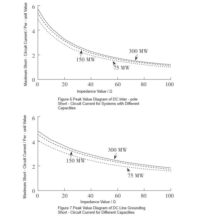
Using the curve-fitting function in MATLAB, the curves in Fig. 6 and Fig. 7 are fitted respectively, resulting in functional expressions of the form f(x) = ae⁻ᵇˣ + c, with specific parameters listed in Table 1. Differentiating the fitted function yields f'(x) = -abe⁻ᵇˣ. From Table 1, it can be observed that for the same fault type, parameter b remains nearly constant, while parameter a increases with system capacity. Since b is relatively small, the slope expressions of the curves for the same fault type are almost identical.Therefore, R-SFCLs with the same normal-state resistance exhibit the same rate of change in peak fault current across different system capacities for the same fault type, indicating consistent current-limiting performance.
Furthermore, as the normal-state resistance of the R-SFCL increases linearly, its current-limiting effectiveness gradually diminishes. Based on the slopes of the curves in Fig. 6 and Fig. 7, the optimal range of the R-SFCL's normal-state resistance for maximizing the rate of reduction in peak fault current is 0–10 Ω.
4 Conclusion
Installing an R-SFCL on the DC output side of a converter station in a flexible DC transmission system can effectively reduce DC short-circuit fault currents. As the resistance value of the R-SFCL increases linearly, its current-limiting effect gradually diminishes. Considering the current research status, engineering costs, and land area requirements, it is recommended that the optimal normal-state resistance range for the R-SFCL be 0–10 Ω.


