Ampere’s circuital law

Rabert T
03/09/2024

WechatIMG1368.jpeg

Ampere’s circuital law is a fundamental law in electromagnetism that relates the magnetic field around a conductor to the electric current flowing through the conductor. It is named after French scientist André-Marie Ampère, who developed the law in the early 19th century.

Ampere’s circuital law Equation:

Ampere’s circuital law can be expressed mathematically as:

Bds = µ0Ienc

where:

∮B⋅ds – The integral of the magnetic field (B) around a closed path (ds)

µ0 – The permeability of free space, a constant value equal to 4π x 10-7 N/A2

Ienc – The total electric current enclosed by the closed path


WechatIMG1369.jpeg


In simpler terms, Ampere’s circuital law states that the magnetic field around a conductor is directly proportional to the electric current flowing through the conductor. This means that if the current flowing through a conductor increases, the magnetic field around the conductor will also increase.

Ampere’s circuital law is a fundamental principle that is used to calculate the magnetic field produced by electric currents and to understand the behavior of electromagnetic systems. It is often used in conjunction with other laws, such as Faraday’s law of electromagnetic induction, to understand the interactions between electric and magnetic fields.

What SI unit is used to describe the Ampere’s circuital law?

According to the International System of Units (SI), which uses newtons per ampere squared or henries per meter as its measurement system.

Ampere’s circuital Law Applications:

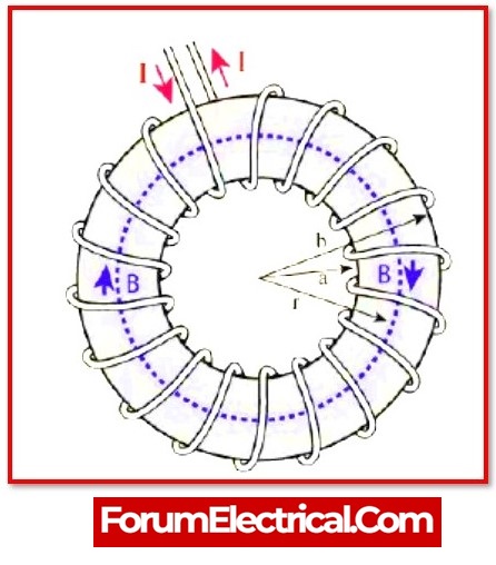
  • The magnetic induction caused by a long wire carrying a current can be calculated.

  • Calculate exactly how much of a magnetic field exists inside a toroid.

  • Calculate the magnetic field generated by a current carrying long conducting cylinder.

  • Finding the strength of the magnetic field within the conductor.

  • Locate the inter-current forces.

WechatIMG1370.jpeg

Statement: Respect the original, good articles worth sharing, if there is infringement please contact delete. 

Rabert T

As an electrical engineer with 5 years of experience, I focus on transformer and circuit breaker reliability in 110/33-11kV and 33/11kV substations. I am a professional electrical engineer with experience in transformer service and maintenance.

Electrical And Electronic Symbols
An electrical symbol is a small image used to represent an electrical or electronic device or function. They are also known as circuit symbols or schematic symbols as they are used in electrical schematics and diagrams.Some basic electrical symbols include: Wires Diode Batteries Transformers Capacitors Resistors Inductors Fuses Switches Bipolar Junction Transistors Electromagnetic RelaysThere are many electrical and circuit symbols used internationally around the world. While they are mostly st
Blake
03/18/2024
Electrical Transformers – Formulas and Equations
Transformers are one of the most common types of electrical devices, and they may be found in a variety of applications within the area of electrical engineering, including power systems. Therefore, in the position of an electrical engineer, it is usually neededto compute various characteristics of a transformer in order to establish the circumstances under which it operates. In order to do this,will need to use conventional equations, which can be seen mentioned in the sections that will follow
Hobo
03/18/2024
Lenz's Law Explained
Lenz's Law, named after the Russian physicist Heinrich Lenz (1804-1865), is a fundamental principle in electromagnetism. It states that the direction of the induced electromotive force (emf) in a closed conducting loop always opposes the change in magnetic flux that caused it. This means that the induced current creates a magnetic field that opposes the initial change in magnetic flux, following the principles of conservation of energy.Understanding Lenz's Law allows us to appreciate the science
The Electricity Forum
03/18/2024
What is Shunt Resistor and How Does it Work?
In several electrical and power applications, the measurement of current flow is essential.Hence, current measurement is commonly required for monitoring and controlling applications.Depending on the kind of application, many types of current sensors with specialised current sensing technologies are available to detect (or)measure current flow.A current sensing resistor, also known as a shunt resistor, is the most prevalent methodto measure current flow in any application.This postdescribes shun
Rabert T
03/12/2024
Inquiry
Download
IEE-Business is dedicated to serving the personnel in the global power industry.
Join IEE-Business, not only can you discover power equipment and power knowledge, but also canhnd like - minded friends!