• Product
  • Suppliers
  • Manufacturers
  • Solutions
  • Free tools
  • Knowledges
  • Experts
  • Communities
Search


Photovoltaic Power Generation Process Common Faults Causes and Solutions

Rockwell
Rockwell
Field: Manufacturing
China

1. Brief Introduction to the Photovoltaic Power Generation Process

The operation process of photovoltaic power generation is as follows: First, individual solar panels are connected in series to form photovoltaic modules, and the modules are arranged in parallel through combiner boxes to form a photovoltaic array. Solar energy is converted into direct current (DC) by the photovoltaic array, and then converted into three-phase alternating current (AC) through a three-phase inverter (DC - AC). Subsequently, with the help of a step-up transformer, it is converted into AC that meets the requirements of the public power grid and directly connected to the public power grid for use by electrical equipment and remote dispatching.

2. Classification of Common Operation Faults in Photovoltaic Power Generation
2.1 Operation Faults of Step-up Stations

Operation faults of step-up stations mainly include transmission line faults, bus faults, transformer faults, high-voltage switch and auxiliary equipment faults, and relay protection device faults.

2.2 Common Operation Faults in Photovoltaic Areas

Operation faults in photovoltaic areas are most commonly caused by irregular construction and installation, leading to faults of solar panels, strings, and combiner boxes; or faults caused by improper installation and commissioning of inverters, as well as faults of auxiliary equipment of step-up transformers; and faults formed due to negligence in personnel inspection and failure to detect hidden dangers in a timely manner.

2.3 Communication and Automation Faults
Communication and automation faults may not affect the power generation of equipment for the time being, but they will bring disadvantages to operation analysis, the detection and elimination of equipment defects. They may also make the equipment unable to be operated remotely, creating hidden dangers for safe production. If not taken seriously, they are likely to cause the expansion of accidents.

2.4 Faults Caused by Region and Environment

Such faults are mainly manifested as: settlement of soft soil foundations causes deformation of equipment and difficulty in operation, and insufficient safety distance causes electrical grounding and short circuits; salt spray corrodes electrical equipment, and water vapor evaporation causes blockage shedding and insulation degradation of equipment; small animals enter electrical equipment and cause short circuits, etc.

3. Analysis of the Causes of Common Faults

Theoretically, various accidents and major faults can be prevented, but in practice, power production safety accidents still occur from time to time, and equipment faults and defects are common. The reasons are as follows:

  • At the initial stage of design, especially in early photovoltaic projects, there are congenital defects. Because the process of photovoltaic power generation is simple and intuitive, the construction once was carried out in a rush, and there was a lack of perfect experience for reference.

  • The rush of the construction period makes it difficult to strictly control the technical management of the construction team, and the construction process and specifications do not meet the standards, leaving hidden dangers for later operation.

  • There is no mature operation inspection mechanism, so it is difficult to identify the quality of equipment suppliers, resulting in poor reliability and high failure rate of equipment in operation.

  • The quality of personnel cannot keep up with the development. Most of the photovoltaic operation and maintenance personnel are new employees, learning while working; some enterprises rely on old employees from thermal power plants to "train new employees with old employees", and new employees have deficiencies in operation analysis, abnormal detection, defect elimination, and accident handling capabilities.

4. Solutions

The technical solutions for common operation faults of photovoltaic power plants are as follows:

  • Start from the source, and at the initial stage of design, make a complete, detailed, scientific and optimized design plan combined with the actual situation of the site.

  • Strengthen the whole-process infrastructure management, strictly check the qualification review, and pay close attention to the process quality and specifications.

  • Strictly control the access of equipment, and resolutely keep unqualified equipment out of the door.

  • Strengthen the education of personnel's sense of responsibility and the cultivation of technical capabilities. Implementing these 4 points can effectively reduce the incidence of common faults.

4.1 Common Faults and Handling of Step-up Stations

Faults of step-up stations belong to general electrical faults, and the handling principles and methods are similar for enterprises of different power generation types. In particular, busbar power failure and line tripping will cause the entire site to lose power for a single-bus single-circuit step-up station; for photovoltaic projects, the inverter needs to start island protection and stop operation. The operation and duty personnel need to:

  • Confirm the factory power supply, check the input of the standby power supply, and ensure the normal operation of the DC and communication systems.

  • Verify the action of protection devices, clarify the type of action, and analyze the possibility of faults.

  • Check the primary system, find out the fault point, cooperate with the dispatch, take safety measures to eliminate defects, and restore operation as soon as possible.

4.2 Common Faults and Causes in Photovoltaic Areas

The inducements of operation faults in photovoltaic areas are mainly as follows:

  • During infrastructure construction, the installation and wiring of solar panels are not firm, some connectors do not use special connectors, the screws in the combiner box are not tightened, and the blocking is incomplete or of poor quality.

  • The installation and commissioning of equipment are not serious and in place. The installation, wiring, and commissioning of inverters and step-up transformers are responsible by different personnel, and lack of unified coordination, so faults are prone to occur frequently.

  • Faults caused by regional environmental characteristics, such as salt spray in coastal tidal flats corroding equipment, causing pollution flashover of cables and insulators, insulation degradation, and equipment short circuits.

  • Faults caused by long-term operation are manifested as loosening caused by equipment rotation and vibration, such as faults of cooling fans of transformers and inverters, loosening of the locking limit of the box transformer grid door, and loosening of the fastening screws and terminal rows of combiner boxes.

4.3 Prevention of Common Faults in Photovoltaic Operation

Faults of step-up stations or equipment in photovoltaic areas all belong to electrical equipment faults. For prevention, it is necessary to:

  • Implement the requirement that infrastructure serves production, and ensure quality and leave no hidden dangers for delivery during construction.

  • In operation, actively implement technical supervision, and take preventive measures in advance according to the characteristics of the site.

  • Strengthen the education of employees' sense of responsibility and the cultivation of problem analysis capabilities.

4.4 Phenomena and Handling of Common Faults in Photovoltaic Operation

After the commissioning and trial operation of equipment in the photovoltaic area are normal, the difficult-to-detect faults often occur in the section from the solar panels to the combiner boxes. There are no obvious phenomena in the initial stage, but the power loss continues. A clamp ammeter can be used to measure the operating current of each string, find out the faulty string, and then check whether it is a fuse problem, a solar panel fault, or a problem such as damage to the connection line of the string, and handle it in a timely manner.

4.4.1 Combiner Box Faults

Common faults of combiner boxes include blockage shedding, communication module faults, and grounding heating and even fire caused by loosening of terminals and screws.
The on-site handling is mainly inspection. During the "spring inspection", the blockage is repaired, and the terminal screws of the combiner box are tightened, which can basically relieve the heating problem in summer.

4.4.2 Inverter Faults

Inverter faults often manifest as shutdown and inability to self-start, mostly occurring in the initial stage of commissioning; after the running-in period, most of them are heat dissipation faults (overtemperature), or accessory damage and software faults.
The key to prevention and handling of inverter faults lies in daily cleaning of the filter screen, ensuring heat dissipation, strengthening the inspection of cooling fans, and timely repairing and replacing when abnormalities are found.

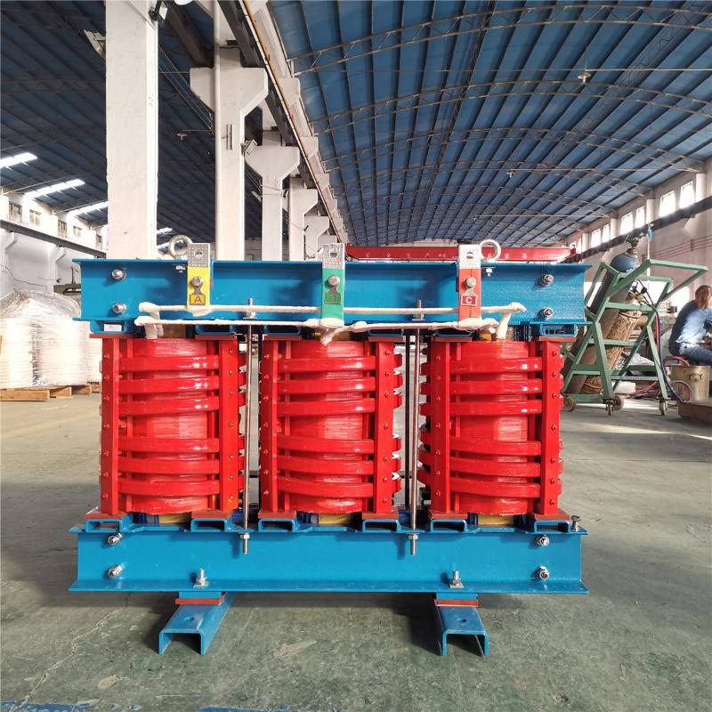
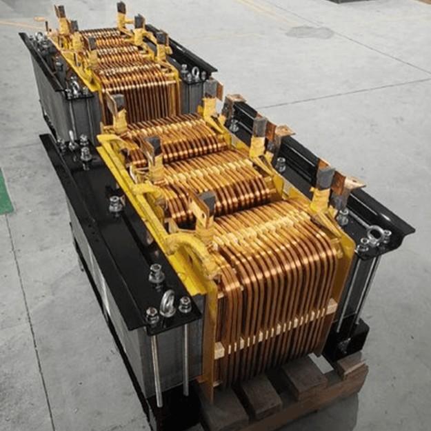
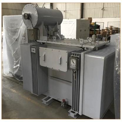
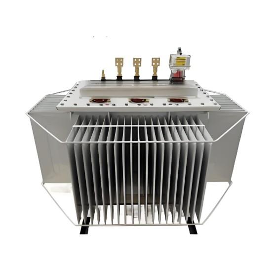
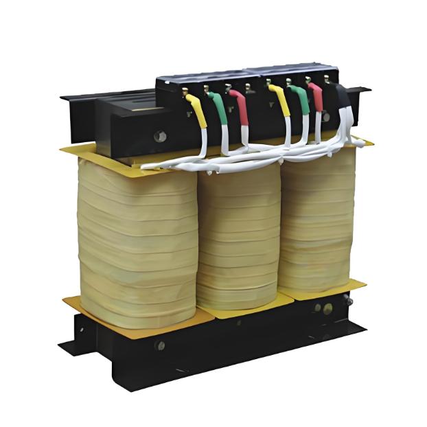
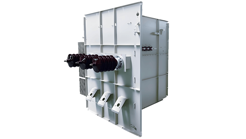
4.4.3 Step-up Transformer Faults

The technology of transformers is mature, and the failure rate of dry-type transformers is extremely low under normal conditions. Common faults include improper blocking leading to the entry of small animals, cooling fan faults, and loosening of the locking of the safety grid door of the main body. In coastal areas and fishery-solar complementary projects, the cable heads, cables, and lightning arresters of the high-voltage switches of step-up transformers are the key inspection items. Once a fault occurs, it will cause the entire collection line to stop operating.
The prevention and handling of step-up transformer faults still rely on daily inspection in place and timely implementation of technical supervision work to prevent problems before they occur.

Give a tip and encourage the author!
Recommended
How to Implement Transformer Gap Protection & Standard Shutdown Steps
How to Implement Transformer Neutral Grounding Gap Protection Measures?In a certain power grid, when a single-phase ground fault occurs on a power supply line, both the transformer neutral grounding gap protection and the power supply line protection operate simultaneously, causing an outage of an otherwise healthy transformer. The main reason is that during a system single-phase ground fault, the zero-sequence overvoltage causes the transformer neutral grounding gap to break down. The resulting
Noah
12/05/2025
Innovative & Common Winding Structures for 10kV High-Voltage High-Frequency Transformers
1.Innovative Winding Structures for 10 kV-Class High-Voltage High-Frequency Transformers1.1 Zoned and Partially Potted Ventilated Structure Two U-shaped ferrite cores are mated to form a magnetic core unit, or further assembled into series/series-parallel core modules. Primary and secondary bobbins are mounted on the left and right straight legs of the core, respectively, with the core mating plane serving as the boundary layer. Windings of the same type are grouped on the same side. Litz wire i
Noah
12/05/2025
How to Increase Transformer Capacity? What Needs to Be Replaced for Transformer Capacity Upgrade?
How to Increase Transformer Capacity? What Needs to Be Replaced for Transformer Capacity Upgrade?Transformer capacity upgrade refers to improving the capacity of a transformer without replacing the entire unit, through certain methods. In applications requiring high current or high power output, transformer capacity upgrades are often necessary to meet demand. This article introduces methods for transformer capacity upgrade and the components that need to be replaced.A transformer is a critical
Echo
12/04/2025
Causes of Transformer Differential Current and Hazards of Transformer Bias Current
Causes of Transformer Differential Current and Hazards of Transformer Bias CurrentTransformer differential current is caused by factors such as incomplete symmetry of the magnetic circuit or insulation damage. Differential current occurs when the primary and secondary sides of the transformer are grounded or when the load is unbalanced.Firstly, transformer differential current leads to energy waste. Differential current causes additional power loss in the transformer, increasing the load on the
Edwiin
12/04/2025
Related Products
Send inquiry
Download
Get the IEE Business Application
Use the IEE-Business app to find equipment, obtain solutions, connect with experts, and participate in industry collaboration anytime, anywhere—fully supporting the development of your power projects and business.