• Product
  • Suppliers
  • Manufacturers
  • Solutions
  • Free tools
  • Knowledges
  • Experts
  • Communities
Search


What are the causes of current transformer faults and the countermeasures for faults?

Felix Spark
Felix Spark
Field: Failure and maintenance
China

As a front - line maintenance technician, I deal with current transformers (CTs) daily. CTs convert high - magnitude primary current to low - magnitude secondary current for substation/line protection and measurement, operating in series long - term. However, they face faults from external (unbalanced loads, wrong wiring, etc.) and internal (insulation defects) issues. These faults, like secondary open - circuits or insulation breakdown, harm measurement accuracy, protection operation, and grid stability. Below, I share insights from hands - on experience.

1. CT Structure (Maintenance View)

A CT has primary/secondary windings, a core, and insulation (oil - immersed, SF6, solid). The primary winds in series with the circuit, the secondary connects to instruments/relays. Key: Fewer primary turns, more secondary turns, and near - short - circuit normal operation. Critical: Never open the secondary circuit; ground it reliably (I’ve seen dangerous arc flashes from open circuits).

2. Function & Principle (Practical)

CTs reduce large currents for safe protection/measurement via electromagnetic induction, isolating high voltage. During calibrations, I check primary - secondary current ratios to verify CTs.

3. Performance Classification
(1) Optical CTs (OTA)

Based on Faraday magneto - optical effect, used in grid tests. Temperature - sensitive but good for strong magnetic fields.

(2) Low - Power CTs

With microcrystalline alloy cores, they offer wide linear ranges, low losses, and high precision for large currents—ideal for industrial measurements.

(3) Air - Core CTs

No iron core, avoiding magnetic saturation. Popular in relay protection for strong anti - interference, suitable for complex environments.

4. Fault Causes (Field Experience)
(1) Insulation Thermal Breakdown

High - voltage CTs generate heat/dielectric losses. Defective insulation (e.g., uneven wrapping) causes overheating and breakdown—common in old equipment.

(2) Partial Discharge

Normal CT capacitance distributes evenly, but poor manufacturing/structure (e.g., misaligned screens) causes local high fields. Unresolved discharges lead to capacitor failures.

(3) Excessive Secondary Load

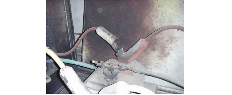
Heavy loads in 220 kV systems increase secondary voltage/current, causing errors. Faults may saturate cores, misoperate relays. Open secondary circuits (e.g., loose wires) create high voltages—risky!

5. Fault Response
(1) Follow Operational Rules

  • Wiring: Strictly series - connect circuits, windings, and instruments; use proper configurations (single - phase, star).

  • Error Compensation: Add windings/cores to correct errors via capacitance/inductance.

  • Calibration: Perform demagnetization/polarity tests post - installation/maintenance.

(2) Emergency Handling (Safety First)

  • Power Off: Immediately cut power for safety.

  • Inspect Secondary Circuit: Check for open circuits, minimize primary current, use insulation gear, and follow diagrams.

For secondary open circuits:

  • Assess Impact: Identify affected circuits, report to dispatch.

  • Reduce Load/Isolate: Transfer loads and de - energize if damaged.

  • Short - Circuit Secondary: Use approved materials; sparks mean downstream faults, no sparks mean upstream issues.

(3) Detection Techniques

  • Insulation Testing: Measure dielectric loss, capacitance to spot defects—good for aging assessment.

  • Infrared Thermography: My key tool! Detects loose connections/thermal issues quickly.

Conclusion

CTs are vital for grid reliability. Mastering their structure, principles, and fault handling ensures stability. Following guidelines, using detection tools, and acting on emergencies minimizes failures—securing a safer grid.

Give a tip and encourage the author!
Recommended
Why Can't VT Be Shorted & CT Be Opened? Explained
We all know that a voltage transformer (VT) must never operate short-circuited, while a current transformer (CT) must never operate open-circuited. Short-circuiting a VT or opening the circuit of a CT will damage the transformer or create hazardous conditions.From a theoretical standpoint, both VTs and CTs are transformers; the difference lies in the parameters they are designed to measure. So why, despite being fundamentally the same type of device, is one prohibited from short-circuit operatio
Echo
10/22/2025
How to Safely Operate & Maintain Current Transformers?
I. Permissible Operating Conditions for Current Transformers Rated Output Capacity: Current transformers (CTs) must operate within the rated output capacity specified on their nameplate. Operation beyond this rating reduces accuracy, increases measurement errors, and causes inaccurate meter readings, similar to voltage transformers. Primary Side Current: The primary current may continuously operate up to 1.1 times the rated current. Prolonged overload operation increases measurement errors and m
Felix Spark
10/22/2025
10kV RMU Common Faults & Solutions Guide
Application Issues and Handling Measures for 10kV Ring Main Units (RMUs)The 10kV ring main unit (RMU) is a common electrical distribution device in urban power distribution networks, primarily used for medium-voltage power supply and distribution. During actual operation, various issues may arise. Below are common problems and corresponding corrective measures.I. Electrical Faults Internal Short Circuit or Poor WiringA short circuit or loose connection inside the RMU can lead to abnormal operati
Echo
10/20/2025
High-Voltage Circuit Breaker Types & Fault Guide
High-Voltage Circuit Breakers: Classification and Fault DiagnosisHigh-voltage circuit breakers are critical protective devices in power systems. They rapidly interrupt current when a fault occurs, preventing damage to equipment from overloads or short circuits. However, due to long-term operation and other factors, circuit breakers may develop faults that require timely diagnosis and troubleshooting.I. Classification of High-Voltage Circuit Breakers1. By Installation Location: Indoor-type: Insta
Felix Spark
10/20/2025
Send inquiry
Download
Get the IEE Business Application
Use the IEE-Business app to find equipment, obtain solutions, connect with experts, and participate in industry collaboration anytime, anywhere—fully supporting the development of your power projects and business.