• Product
  • Suppliers
  • Manufacturers
  • Solutions
  • Free tools
  • Knowledges
  • Experts
  • Communities
Search


What is Insulation Co-ordination?

Edwiin
Edwiin
Field: Power switch
China

Definition: Insulation coordination refers to the process of determining the insulation levels of power system components. In essence, it is about establishing the insulation strength of equipment. The internal and external insulation of electrical equipment is subjected to both continuous normal voltage and temporary abnormal voltage.

Equipment insulation is engineered to withstand the highest power - frequency system voltage, occasional temporary power - frequency overvoltages, and occasional lightning surges. Power system equipment is assigned a rated insulation level, and its performance can be verified through various types of tests. The insulation requirements are determined by taking into account the following factors:

Highest Power - Frequency System Voltage

AC power networks feature different nominal power - frequency voltage levels, such as 400V, 3.3KV, 6.6kV, etc. When the system is lightly loaded, the power - frequency voltage at the receiving end of the line increases. Power system equipment is designed and tested to endure the highest power - frequency system voltage (440V, 3.6KV, 7.2KV, etc.) without experiencing internal or external insulation breakdown.

Temporary Power - Frequency Overvoltages

Temporary overvoltages in the power system can be triggered by load rejection, faults, resonance, etc. These overvoltages typically have a frequency of around 50 Hz, with relatively lower peaks, a slower rate of rise, and a longer duration (ranging from seconds to even minutes). Protection against temporary power - frequency overvoltages is provided by an Inverse Definite Minimum Time (IDMT) relay.

The IDMT relay is connected to the secondary of the bus potential transformer and circuit breakers. The relay and circuit breaker respond within milliseconds, safeguarding the system from temporary overvoltages.

Transient Overvoltage Surges

Transient overvoltage surges in the power system can be induced by phenomena such as lightning, switching operations, restrikes, and travelling waves. These surges in the power system are characterized by high peak values, a rapid rate of rise, and a duration lasting for a few tens to hundreds of microseconds, which is why they are referred to as transients.

Such surges have the potential to cause spark - over voltages and flash - overs at sharp corners, between phases and the earth, or at the weakest points in the system. They can also lead to the breakdown of gaseous, liquid, or solid insulation, as well as the failure of transformers and rotating electrical machines.

Through proper insulation coordination and the use of surge arresters, the failure rates caused by lightning and switching operations have been significantly reduced. Various protective devices are installed on the power network. These devices are designed to intercept lightning strikes and to decrease the peak rate of rise of surges that reach the equipment, thereby safeguarding it from potential damage.

Equipment Withstand Levels

The basic insulation level (BIL) is a reference level, represented by the impulse crest voltage of a standard wave not exceeding 1.2/50 μs. Apparatus and equipment must be able to withstand test waves with amplitudes greater than the BIL.

Insulation coordination involves choosing appropriate insulation for equipment based on its intended use. This is done to minimize unwanted events within the system that result from voltage stresses (caused by system overvoltages). Insulation breakdown refers to the relationship between the insulation breakdown of various power system components and the insulation of protective devices employed to safeguard that equipment against overvoltages.

For the safe operation of equipment, its insulation strength shall be equal to or higher than the basic standard insulation level. Protective equipment for station substations should be selected to provide effective insulation protection corresponding to these levels while being as economical as possible.

Give a tip and encourage the author!
Recommended
Composition and Working Principle of Photovoltaic Power Generation Systems
Composition and Working Principle of Photovoltaic (PV) Power Generation SystemsA photovoltaic (PV) power generation system is primarily composed of PV modules, a controller, an inverter, batteries, and other accessories (batteries are not required for grid-connected systems). Based on whether it relies on the public power grid, PV systems are divided into off-grid and grid-connected types. Off-grid systems operate independently without relying on the utility grid. They are equipped with energy-s
Encyclopedia
10/09/2025
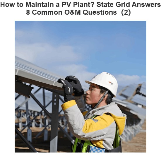
How to Maintain a PV Plant? State Grid Answers 8 Common O&M Questions(2)
1. On a scorching sunny day, do damaged vulnerable components need to be replaced immediately?Immediate replacement is not recommended. If replacement is necessary, it is advisable to do so in the early morning or late afternoon. You should contact the power station’s operation and maintenance (O&M) personnel promptly, and have professional staff go to the site for replacement.2. To prevent photovoltaic (PV) modules from being hit by heavy objects, can wire mesh protective screens be install
Encyclopedia
09/06/2025
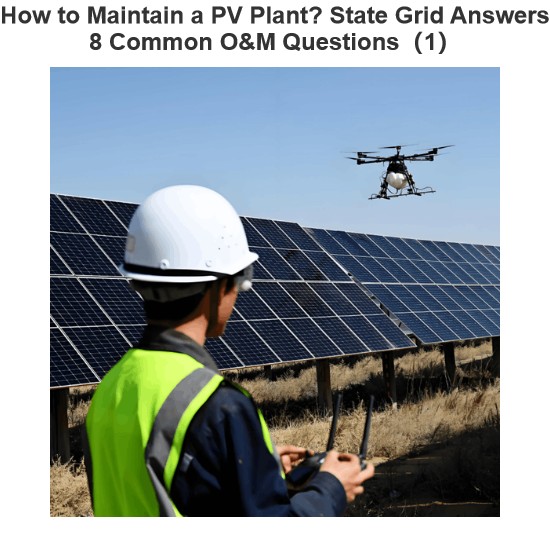
How to Maintain a PV Plant? State Grid Answers 8 Common O&M Questions(1)
1. What are the common faults of distributed photovoltaic (PV) power generation systems? What typical problems may occur in various components of the system?Common faults include inverters failing to operate or start due to voltage not reaching the startup set value, and low power generation caused by issues with PV modules or inverters. Typical problems that may occur in system components are burnout of junction boxes and local burnout of PV modules.2. How to handle common faults of distributed
Leon
09/06/2025
Short Circuit vs. Overload: Understanding the Differences and How to Protect Your Power System
One of the main differences between a short circuit and an overload is that a short circuit occurs due to a fault between conductors (line-to-line) or between a conductor and earth (line-to-ground), whereas an overload refers to a situation where equipment draws more current than its rated capacity from the power supply.Other key differences between the two are explained in the comparison chart below.The term "overload" typically refers to a condition in a circuit or connected device. A circuit
Edwiin
08/28/2025
Send inquiry
Download
Get the IEE Business Application
Use the IEE-Business app to find equipment, obtain solutions, connect with experts, and participate in industry collaboration anytime, anywhere—fully supporting the development of your power projects and business.