
Årsager til fejl i fordelingstransformatorer
Fejl forårsaget af temperaturstigning
Indvirkning på metalmaterialer
Når en transformator er i drift, og hvis strømmen er for stor, sådan at kundens belastning overstiger den nominale kapacitet for transformator, vil temperaturen i transformator stige, hvilket på sin side blidgør metalmaterialerne og reducerer deres mekaniske styrke betydeligt. Tag koppar som eksempel. Hvis det udsættes for et højt temperaturmiljø over 200 °C i lang tid, vil dets mekaniske styrke være betydeligt svækket; hvis temperaturen overskrider 300 °C i kort tid, vil mekanisk styrken også falde skarpt. For aluminiumsmaterialer skal den langvarige arbejdstemperatur kontrolleres under 90 °C, og den kortvarige arbejdstemperatur bør ikke overskride 120 °C.
Indvirkning af dårlig kontakt
Dårlig kontakt er en vigtig årsag til mange fejl i fordelingsudstyr, og temperaturen på elektriske kontaktpartier har stor indflydelse på kvaliteten af elektrisk kontakt. Når temperaturen er for høj, vil overfladen af elektriske kontaktledere oksideres voldsomt, og kontaktmodstanden vil øges betydeligt, hvilket vil føre til, at temperaturen på ledere og deres komponenter stiger, og i alvorlige tilfælde kan kontakterne blive forsynt sammen.
Indvirkning på isoleringsmaterialer
Når ambienttemperaturen overstiger det rimelige område, vil organiske isoleringsmaterialer blive sprøde, hvilket accelererer deres ældningsproces, og fører til en betydelig nedgang i isoleringskapaciteten, og i alvorlige tilfælde kan dielektrisk gennembrud opstå. Studier har vist, at for klasse A-isoleringsmaterialer, inden for deres temperaturbestandighedsområde, vil en stigning i temperaturen med 8-10 °C reducere materialets effektive levetid med næsten halvdelen. Dette forhold mellem temperatur og levetid kaldes "termisk ældningsvirknings", som er en vigtig faktor, der påvirker pålideligheden af isoleringsmaterialer.
Fejl i fordelingstransformatorer forårsaget af dårlig kontakt
Fejl forårsaget af oksidering af beskyttelsesbelægninger
For at forbedre den samlede ydeevne af lederkomponenter anvendes ofte overfladefrembringende teknologier i ingeniørpraksis til behandling af nøglekontaktpartier. Tag for eksempel en lederstab i en transformator. En edelmetalsbeskyttelseslag (som guld, sølv eller tinbaserede legemer) dannes normalt på dens arbejdsoverflade gennem elektroplatering. Dette metallurgiske bindingsskikt kan betydeligt forbedre de fysiske og kemiske egenskaber ved kontaktgrænsefladen.
Det skal bemærkes, at under mekanisk drift i udstyrsvedligeholdelse eller under langvarig termisk belastning kan belægningen delvist løsne eller udsættes for oksidering og korrosion, hvilket på sin side kan forårsage problemer som abnorm stigning i kontaktmodstand og reduktion i strømførende kapacitet. Eksperimentelle data viser, at når tykkelsetab ved belægningen overstiger 30%, vil elektrisk konduktivitetsstabiliteten i grænsefladen vise en eksponentiel nedgangstrend.
Kemisk korrosion forårsaget af direkte forbindelse mellem koppar og aluminium
I et elektrisk forbindelsessystem vil direkte kontakt mellem ulige metaller som koppar og aluminium danne en betydelig elektrodpotentialforskelsværdi, og dens potentialeværdi kan nå 0,6-0,7 V. Denne potentialforskel vil udløse alvorlig galvanisk korrosion. I ingeniørpraksis forekommer direkte forbindelse mellem koppar- og aluminiumledere uden overgangsbehandling ofte pga. manglende overholdelse af konstruktionsregler eller forkert materialevalg.
Efter denne forbindelsesmetode er energiseret, vil der gradvist dannes et oksideringsfilm-lag ved kontaktgrænsefladen, hvilket resulterer i en ikke-lineær stigning i kontaktmodstanden. Under den nominale arbejdstemperatur er den effektive levetid for sådanne forbindelser normalt ikke mere end 2000 timer, og til sidst vil fejl opstå pga. forringelse af kontaktfladen.
Alvorlig opvarmning ved elektriske kontakter forårsaget af dårlig kontakt
Under den faktiske installation af fordelingstransformatorer konfigureres der normalt antyvermeterkasser på lavspændings siden. På grund af begrænsede interne rum i meterkassen og ikke-standardiserede konstruktionsmetoder, opstår der ofte problemer som forvikling af ledere eller løse mekaniske krøblinge af terminalblokke. Disse dårlige forbindelser vil føre til en abnorm stigning i kontaktmodstanden, hvilket vil forårsage overophedning under virkningen af belastningsstrømmen, og derefter udløse ablative fejl af lavspændingslederstangen.
Endnu alvorligere vil den fortsatte temperaturstigning ved enden af lavspændingsvindingen accelerere den termiske ældningsproces af isoleringsmaterialet, og skabe potentielle farer for lokal udladning. Samtidig vil overophedning også få transformerolie til at udføre en pyrolysereaktion, hvilket nedsætter dets isoleringsstyrke og kølevirkning. Eksperimentelle data viser, at når oljetemperaturen konstant overstiger 85 °C, vil dens nedbrydningsvoltage falde med ca. 15% - 20% pr. år. Denne multiple forringelseseffekt er meget sandsynlig at forårsage isoleringsnedbrydningshændelser, når der opstår lynovervoltage eller skifterovervoltage, og dette vil til sidst føre til fiaskoen af transformator.
Fejl i fordelingstransformatorer forårsaget af fugt
En stigning i den relative luftfugtighed i miljøet har en dobbelt indvirkning på isoleringssystemet i fordelingsudstyr. For det første falder dielektriske styrken af fugtig luft betydeligt, og dens nedbrydningsfeltstyrke er negativt korreleret med fugtighed; for det andet vil absorptionen af vandmolekyler på overfladen af isoleringsmaterialer danne ledende kanaler, hvilket fører til en reduktion i overfladeresistansen. Endnu alvorligere, når fugt diffuse ind i indersiden af faste isoleringsmedier eller løses i transformerolie, vil det forårsage en skarp stigning i dielektriske tab.
Når vandindholdet i transformerolie når ca. 100 μL/L, vil dets netfrekvens-nedbrydningsvoltage falde til ca. 12,5% af den initiale værdi. Denne forringelse af isoleringskapaciteten vil betydeligt øge udstrømningsstrømmen i udstyret. I et fugtigt miljø kan der opstå lokale udladninger selv under den nominale driftsspanning. Statistikker viser, at i et miljø med en relativ luftfugtighed, der overstiger 85%, øges fejlhyppigheden for fordelingstransformatorer med 3-5 gange sammenlignet med i et tørt miljø, primært som isoleringsnedbrydning og overfladeflaskehændelser.
Fejl i fordelingstransformatorer forårsaget af forkert installation af lynbeskyttelsesapparater
I strømsystemet har pålideligheden af overvoltagebeskyttelsesenheder direkte indflydelse på driftssikkerheden af transformatorer. Som de hovedsagelige beskyttelseskomponenter er installationskvaliteten, drift og vedligeholdelse, samt forebyggende tests af metaloksidblitzabledere (MOA) de vigtige led, der sikrer deres effektivitet. Imidlertid, pga. ikke-standardiserede konstruktionsmetoder, utilstrækkelig implementering af testprocedurer, og mangel på professionel kompetence hos drifts- og vedligeholdelsespersonale, er den faktiske beskyttelseseffekt af beskyttelsesenheder ofte betydeligt nedsat, hvilket er en vigtig årsag til isoleringsnedbrydningshændelser i fordelingstransformatorer.
Fra synsvinkel af driftspraksis vil beskyttelsesenheder blive påvirket af forskellige miljøstresser under langvarig service. Faktorer som temperaturcyklusser, mekaniske vibrationer, og korrosive medier kan føre til forringelse af jordforbindelsens forbindelsesegenskaber. Når systemet udsættes for lynslag, vil den mislykkede jordforbindelse ikke kunne aflednings overvoltageenergien i tide, hvilket resulterer i termisk nedbrydning af selve beskyttelsesenheten. Ifølge statistikker udgør eksplosionsulykker forårsaget af dårlig jordforbindelse mere end 60% af fejltilfældene for beskyttelsesenheder, og energifrigørelsesprocessen er ofte ledsaget af intens buelav.
Nogle fejldiagnosemetoder for fordelingstransformatorer
Fejldiagnose gennem直观判断
通过外部特征可以初步判断配电变压器的故障。观察内容包括:外壳完整性(裂纹、变形)、机械状态(紧固件松动)、密封性能(泄漏痕迹)、表面状况(污垢程度、腐蚀现象)以及异常迹象(颜色变化、放电痕迹、冒烟等)。这些外部特征与内部故障有特定的对应关系。
当变压器油呈现深棕色并伴有烧焦味,伴随异常温升和高压侧保护组件动作时,通常表明磁路系统存在异常,可能是硅钢片之间的绝缘损坏或多点接地故障。
如果运行电流异常增加,油温显著上升,三相参数不对称,并伴有低压侧保护装置动作、储油柜冒烟及二次电压波动,则可判定为绕组导体间绝缘失效引起的匝间短路故障。当某一相的电气参数完全消失(电压和电流为0)时,该特征通常对应于绕组开路或连接导体熔断故障。
储油柜喷油现象是变压器严重内部故障的重要标志。当故障产气速率超过压力释放装置的处理能力时,油箱内将形成正压。最初表现为密封薄弱点处的泄漏。随着压力继续升高,最终可能在油箱体接合面处发生喷油。这种故障多由绕组相间绝缘击穿引起,通常伴有高压侧保护组件熔断。根据气体继电器动作统计,约75%的严重故障会经历这一发展过程。
Fault Diagnosis through Temperature Changes
During the operation of distribution transformers, the current-carrying conductors will inevitably generate heat losses due to the Joule effect, which is a normal physical phenomenon. However, when the equipment has electrical abnormalities (such as insulation degradation, poor contact) or mechanical defects (such as winding deformation, cooling system failure), its thermal equilibrium state will be disrupted, manifested as the operating temperature exceeding the designed allowable value. According to the thermal aging theory, for every 6 - 8 °C increase in temperature, the aging rate of insulation materials will double, thus significantly affecting the service life of the equipment.
For abnormal temperature rises caused by internal faults, there are usually obvious abnormalities in the oil circuit system. When the hot-spot temperature reaches the critical value, the transformer oil will undergo a pyrolysis reaction, generating a large amount of gas, causing the pressure relief device to operate, resulting in oil leakage or oil spraying. In engineering practice, a simple method can be used to initially judge the temperature status of the equipment: if the surface of the transformer casing can be touched by hand for more than 10 seconds, its surface temperature usually does not exceed 60 °C. This empirical value can be used as a reference for on-site rapid assessment.
Fault Diagnosis through Odor Changes
The moment the cover of the oil pillow is opened, a peculiar pungent burnt smell can be smelled. This indicates that the coil inside the transformer is burned, often accompanied by the fusing of two to three-phase drop-out fuses.
Fault Diagnosis through Sound Changes
During the operation of a transformer, the magnetostriction effect generated by the magnetization of the iron core will trigger periodic mechanical vibrations. These vibrations and their accompanying acoustic characteristics serve as important indicators of the normal operation of the equipment. Acoustic diagnosis technology enables effective monitoring of the operating status of the transformer. Specifically, the frequency characteristics of the sound signal, changes in the sound pressure level, and the vibration spectrum characteristics can reveal potential faults of the equipment.
When using the acoustic detection method, a conductive rod (such as an insulating rod) can be employed as a medium for sound wave conduction. One end of the rod is brought into contact with the equipment's outer shell, and the other end is placed close to the auditory organ for listening. Once abnormal sound signals are detected, preventive maintenance measures should be promptly implemented to prevent the escalation of faults. The following are the correspondences between typical acoustic characteristics and fault types:
Intermittent "clicking" sounds: Usually, this indicates that the iron core laminations are loose or that the fasteners have insufficient torque. The sound pressure level generally falls within the range of 60 to 70 decibels.
High-frequency discharge sounds: Accompanying partial discharge phenomena, the sound signals exhibit a "cracking" characteristic. In severe cases, the sound pressure level can exceed 85 decibels, and visible discharge marks are often present.
Sudden explosive sounds: These mostly occur when the insulation of the leads is damaged or there is a discharge to the ground. The sudden change in the sound pressure level exceeds 20 decibels.
Low-frequency rumbling sounds: Commonly associated with low-voltage side grounding faults, the frequency of the sound signals is concentrated within the range of 100 to 400 hertz.
Sharp whistling sounds: This indicates that the equipment is in an over-excitation state, and the main frequency of the sound signals is typically between 1 and 2 kilohertz.
Bubble boiling sounds: Accompanying abnormal increases in the oil temperature, the sound signals display a continuous "gurgling" characteristic, usually indicating the deterioration of the oil insulation performance.
Fault Diagnosis through Instruments
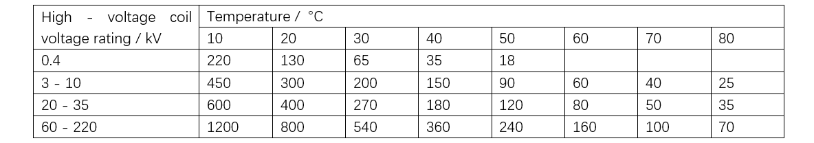
Due to the constraints of equipment technology, power supply stations mostly use a multimeter to measure whether the resistance of the winding conductors is conducting to determine whether there are broken wires or turn-to-turn short-circuits inside the transformer; an insulation resistance tester is used to measure the insulation resistance of each winding of the transformer to the ground, so as to determine whether the main insulation is broken down. When the insulation between the winding and the ground or between phases is broken down, its insulation impedance value will approach 0 Ω.
When testing the insulation performance of the winding, the insulation parameters of the following three circuits need to be measured respectively: the insulation resistance between the primary winding, the secondary winding, and the casing; the insulation resistance between the secondary winding, the primary winding, and the casing; and the insulation resistance between the primary winding and the secondary winding. It should be noted that the reference ground potential point in the test is the metal casing structure of the transformer. The reference values of the insulation resistance of oil-immersed transformers are shown in Table 1.
Fault Diagnosis Technologies for Distribution Transformers
Fault diagnosis technologies for distribution transformers are crucial means to ensure the safe operation of equipment. Through advanced diagnosis technologies, potential faults can be detected in a timely manner, and effective measures can be taken to prevent the expansion of faults. The following introduces several commonly-used fault diagnosis technologies for distribution transformers.
Winding DC Resistance Test
The winding DC resistance test is one of the basic methods for detecting the health status of transformer windings. By measuring the DC resistance of the winding, it is possible to determine whether there are problems such as broken wires, poor contact, or turn-to-turn short-circuits in the winding. For example, during routine inspection of a transformer in a certain area, an abnormal DC resistance of the high-voltage side winding was detected. Further inspection revealed a turn-to-turn short-circuit in the winding. Timely replacement of the winding avoided the occurrence of a more serious fault. The winding DC resistance test has the advantages of simple operation and intuitive results, and it is an indispensable detection method in the daily maintenance of transformers.
Dissolved Gas Analysis (DGA)
Dissolved Gas Analysis (DGA) is an important technical means for diagnosing internal faults of transformers. By analyzing the components and contents of gases dissolved in the transformer oil, it is possible to determine whether there are faults such as overheating and discharge inside the transformer. Using the IEC60599 three-ratio method, discharge-type faults can be accurately identified. For example, high concentrations of acetylene (C2H2) and hydrogen (H2) were detected in the oil of a certain transformer. Analysis by the three-ratio method determined it to be a discharge-type fault. Timely maintenance avoided equipment damage. DGA has the advantages of high sensitivity and accurate diagnosis, and it is an important means for monitoring the condition of transformers.
Partial Discharge Detection
Partial discharge detection is an important method for evaluating the insulation condition of transformers. Partial discharge usually occurs in weak insulation areas, and long-term discharge will lead to the gradual deterioration of insulation materials, ultimately causing serious faults. Through partial discharge detection, insulation defects can be detected in a timely manner, and preventive measures can be taken. For example, during partial discharge detection of a certain transformer, a discharge phenomenon was found in the high-voltage bushing. After replacing the bushing, the discharge phenomenon disappeared, effectively extending the service life of the equipment. Partial discharge detection has the advantages of non-destructiveness and high sensitivity, and it is an important means for monitoring the insulation of transformers.
Combined Vibration and Acoustic Detection
Combined vibration and acoustic detection is to determine whether there are mechanical faults inside the equipment by analyzing the vibration and sound signals during the operation of the transformer. For example, for a faulty transformer, the vibration amplitude exceeded the standard by 3 dB in the 125 Hz frequency band. Inspection revealed that the iron core clamp was loose. After timely tightening, the vibration returned to normal. Combined vibration and acoustic detection has the advantages of real-time monitoring and accurate diagnosis, and it is an important means for diagnosing mechanical faults of transformers.
Infrared Thermography Detection
Infrared thermography detection is to determine whether there are overheating faults in the equipment by detecting the temperature distribution on the surface of the transformer. For example, during infrared thermography detection of a certain transformer, an abnormal temperature was found at the connection of the high-voltage bushing. Inspection revealed that the connection bolts were loose. After timely tightening, the temperature returned to normal. Infrared thermography detection has the advantages of non-contact and rapid diagnosis, and it is an important means for diagnosing overheating faults of transformers.
Fault Elimination Methods and Examples for Distribution Transformers
Line Tripping Caused by Turn-to-Turn Short-Circuit in Transformer
Fault Phenomenon
An over-current trip occurred on a 10 kV line in a certain substation. After reducing part of the load, over-current still occurred during the trial re-closing.
Fault Cause Analysis
After the on-site maintenance personnel arrived at the fault area, they first used a megohmmeter to test the insulation performance of the power supply line, and the measured insulation value to the ground was about 2 MΩ. Subsequently, a monitoring instrument was connected to the open-delta terminal of the secondary side of the 10 kV voltage transformer. During the temporary energization test, the voltage reading was observed to be about 40 V. Combining the on-site investigation results, no new electrical equipment was connected to this line before the fault occurred.
Based on this, the possibility of over-current protection action caused by overload was excluded. According to the analysis of normal operating parameters, this line should neither trigger over-current protection nor have a single-phase grounding anomaly. Through systematic detection and comprehensive judgment, it was initially determined that the root cause of the fault might be the turn-to-turn insulation breakdown in the internal winding of a certain distribution transformer. After analysis, it was possible that there was a turn-to-turn short-circuit fault in a certain distribution transformer of this line. Therefore, the line was transferred from operation to maintenance, and the line inspection was notified.
Further inspection revealed that there was a turn-to-turn short-circuit in phase A of the high-voltage side of a 250 kV·A distribution transformer of a customer on this line, which was the real cause of the trip. The following analyzes the over-current and false grounding situations caused by the turn-to-turn short-circuit of this distribution transformer. Because of the turn-to-turn short-circuit inside the distribution transformer, the simplified equivalent circuit is shown in Figure 1.
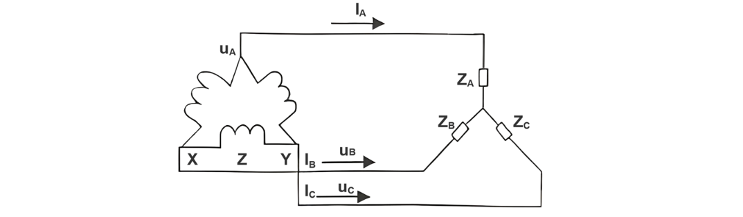
Let ZA, ZB, and ZC be the impedances of phases A, B, and C of the distribution transformer respectively. UO is the neutral point potential. When the three-phase load is balanced, UO = 0; when the three-phase load is unbalanced, UO≠0, resulting in neutral point displacement. When there is a phase-to-phase short circuit in phase A of the distribution transformer, the value of impedance ZA will decrease, and the value of IA will increase. When the sum of IA and the currents of phase A of other distribution transformers on this line is greater than the over-current operating value Idz of the relay protection, an over-current trip will occur. When there is a turn-to-turn short circuit in a certain transformer on phase A of the line, the impedance ZA of phase A of this transformer will decrease, and the voltage on the open delta side of the TV will rise. When this voltage exceeds the setting value of the relay, the central signal in the control room will send out a 10 kV grounding signal.
Accidents Caused by the Contact between the Low-Voltage Wire of the Transformer and its Shell
Fault Phenomenon
A 10 kV/400 V, 100 kV・A transformer in a certain unit supplies power to the load through two circuits on the low-voltage side. Since there is no power consumption load in one of the feeder circuits on the low-voltage side, it is decided to remove this line. After the wire removal work is completed, the power supply is restored. When the high-voltage drop-out fuses of phase A and phase C are closed, there is no abnormal phenomenon. However, when the drop-out fuse of phase B is closed, a huge arc suddenly occurs about 15 cm above the upper cover of the transformer, and then the transformer oil is ejected.
Fault Cause Analysis
After the accident occurs, a comprehensive understanding of the wire removal work is carried out, and a core lifting inspection of the transformer is conducted. During the inspection, it is found that the lead wire on the low-voltage side of phase B directly touches the shell, and there is a hole with a diameter of 1 cm at the contact point. The cause of the accident is that during the wire removal on the low-voltage side, the construction personnel accidentally rotate the screw of the low-voltage terminal of the transformer without noticing, resulting in the lead wire of phase B touching the shell of the transformer. Both the neutral point and the shell of this transformer are directly grounded, so the contact point between the lead wire of phase B and the shell becomes a grounding short-circuit point.
Treatment Countermeasures
First, the hole in the transformer body is repaired by welding. Then, the screw of the low-voltage lead wire connection is tightened. After that, the transformer oil is filtered, and the oil level is replenished to the safe level. After passing the test, the power supply is restored. In order to prevent such accidents, during the connection and disconnection of the transformer, the rotation of the connection screw should be avoided as much as possible. Once the screw rotates, strict treatment must be carried out. Only after confirming that there is no error can the transformer be put into use.
Faults Caused by the Blockage of the Transformer Breather Hole


