• Product
  • Suppliers
  • Manufacturers
  • Solutions
  • Free tools
  • Knowledges
  • Experts
  • Communities
Search


Ultimate Guide to AC Contactor Abnormal Noise: From Electromagnetic Noise to Mechanical Vibration, Accurate Diagnosis and Handling

Felix Spark
Felix Spark
Field: Failure and maintenance
China

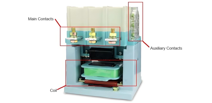
In electrical control systems, AC contactors are among the commonly used electrical components, and they are also a common source of various electrical faults. After long-term use—especially in harsh environments with high levels of dust—AC contactors may sometimes emit squeaking or rattling noises after being pulled in and held. The causes of this phenomenon are analyzed as follows.

AC Contactor.jpg

Squeaking Noise After Pull-In and Holding

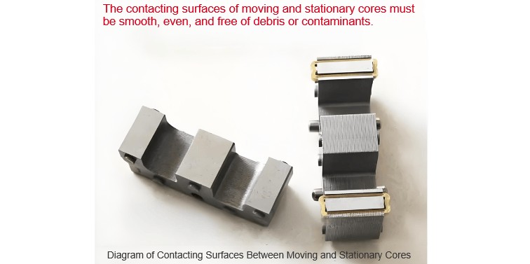
A fully functional AC contactor makes no noise when energized and pulled in. If a squeaking noise occurs during pull-in, the causes include: dirt on the surfaces of the moving iron core and static iron core; uneven force on the compression spring for resetting the moving iron core; or unsmooth movement path of the moving iron core.

AC Contactor.jpg

These issues result in poor contact and gaps between the surfaces of the moving iron core and static iron core, which increases the magnetic resistance of the magnetic circuit and reduces the magnetic attraction force. To counteract this, the current in the coil increases to prevent the magnetic attraction force from decreasing, and this adjustment process repeats continuously. The squeaking noise is exactly the resonance caused by the coil current noise and the vibration of the reset compression spring— the larger the gap between the moving iron core and static iron core, the louder the squeaking noise.

Consequences

a. The AC contactor coil may burn out.

b. Poor contact may occur between the main and auxiliary contacts. In particular, the main contacts bear a large load, making them prone to arc generation, which can burn the main contacts or cause uneven adhesion. Additionally, phase loss may occur, leading to phase-loss operation of the three-phase load (e.g., an electric motor) and even burning of the three-phase load. If the auxiliary contacts are used in other branches, the normal operation of those branches will be affected.

Therefore, once an AC contactor emits a squeaking noise, it should be addressed immediately.

AC Contactor.jpg

II. Rattling Noise During Pull-In

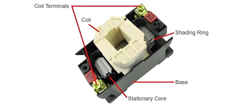
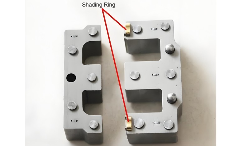
When an AC contactor pulls in, a rattling noise occurring 100 times per second is caused by an open circuit in the short-circuit ring of the contactor’s static (or moving) iron core.

Alternating current with a frequency of 50 Hz crosses zero 100 times per second. At the zero-crossing point, the magnetic force generated by the closed magnetic circuit formed by the moving and static iron cores also drops to zero. The function of the short-circuit ring (installed on the static or moving iron core) is to generate a counter electromotive force when the alternating current crosses zero. This counter electromotive force induces a current in the short-circuit ring, and the current produces a magnetic field that keeps the moving and static iron cores pulled together.

Core Physical Diagram.jpg

Once the short-circuit ring has an open circuit, its maintaining function is lost. At the zero-crossing point, the moving iron core is released under the action of the reset compression spring; after the zero-crossing point, the moving and static iron cores pull together again. This cycle repeats continuously, producing a rattling noise 100 times per second—which is the impact sound generated when the moving and static iron cores pull together.

Consequences

The connected three-phase load will be in a state of repeated starting and stopping, which easily damages the load. The consequences caused by auxiliary contacts are the same as those mentioned above.

In such cases, replace the AC contactor, or temporarily use a copper wire to make a short-circuit ring as a substitute.

Give a tip and encourage the author!
Recommended
10kV RMU Common Faults & Solutions Guide
Application Issues and Handling Measures for 10kV Ring Main Units (RMUs)The 10kV ring main unit (RMU) is a common electrical distribution device in urban power distribution networks, primarily used for medium-voltage power supply and distribution. During actual operation, various issues may arise. Below are common problems and corresponding corrective measures.I. Electrical Faults Internal Short Circuit or Poor WiringA short circuit or loose connection inside the RMU can lead to abnormal operati
Echo
10/20/2025
High-Voltage Circuit Breaker Types & Fault Guide
High-Voltage Circuit Breakers: Classification and Fault DiagnosisHigh-voltage circuit breakers are critical protective devices in power systems. They rapidly interrupt current when a fault occurs, preventing damage to equipment from overloads or short circuits. However, due to long-term operation and other factors, circuit breakers may develop faults that require timely diagnosis and troubleshooting.I. Classification of High-Voltage Circuit Breakers1. By Installation Location: Indoor-type: Insta
Felix Spark
10/20/2025
10 Prohibitions for Transformer Installation and Operation!
10 Prohibitions for Transformer Installation and Operation! Never install the transformer too far away—avoid placing it in remote mountains or wilderness. Excessive distance not only wastes cables and increases line losses, but also makes management and maintenance difficult. Never choose transformer capacity arbitrarily. Selecting the right capacity is essential. If the capacity is too small, the transformer may be overloaded and easily damaged—overloading beyond 30% should not exceed two hours
James
10/20/2025
How to Maintain Dry-Type Transformers Safely?
Maintenance Procedures for Dry-Type Transformers Put the standby transformer into operation, open the low-voltage side circuit breaker of the transformer to be maintained, remove the control power fuse, and hang a "DO NOT CLOSE" sign on the switch handle. Open the high-voltage side circuit breaker of the transformer under maintenance, close the grounding switch, fully discharge the transformer, lock the high-voltage cabinet, and hang a "DO NOT CLOSE" sign on the switch handle. For dry-type trans
Felix Spark
10/20/2025
Send inquiry
Download
Get the IEE Business Application
Use the IEE-Business app to find equipment, obtain solutions, connect with experts, and participate in industry collaboration anytime, anywhere—fully supporting the development of your power projects and business.