Nun da industriya na kashi ta gudana da yawa, an yi amfani da misaloli na karfi, kadan ciki, da hankali ga al'adu a wajen gwargwadon kayan abokan kashi da kuma kayan abokin kashi. Ring Main Unit (RMU) shi ne wuri mai mahimmanci a tashar kayan abokan kashi. Hukuma, hankali ga al'adu, ingancin aiki, kadan ciki, da kuma tattalin arziki suna da muhimmanci a cikin tushen. RMUs na gargajiya sun hada da RMUs mai gas SF6. Saboda ingancin aiki na SF6 da kuma ƙarfinsa mai ƙarin, ana amfani da su da yawa. Amma, SF6 ya haɗa da yanayi na greenhouse. Ba wasu hanyoyin masu tsohon lura na greenhouse, an bukata a yi kayan abokin kashi mai gas mai kyau don zama ƙaramin SF6.
Yanzu, akwai RMUs mai gas nitrogen da kuma RMUs mai gas dry air. An bayyana wasu ɗaya daga cikinsu a littattafai. Idan a bincika ƙarfinsa, ƙarfinsa na nitrogen da dry air yana ƙarin da kusan ɗaya zuwa gas SF6. Saboda haka, yana da muhimmanci a ƙara ƙarfinsa ta RMU da kuma fadin da ake aiki a cikinta ba su ci ƙarin ba saboda ƙarin ƙarfinsa, inda ake ƙara tsari, yana da muhimmanci. Wannan yana nuna a cikin ƙwalba kayan abokin kashi da ƙarfinsa. Ƙwalbar kayan abokin kashi da ƙarfinsa mai daidai zai iya ƙara ƙaramin ƙarfinsa na gas.
Littafi ɗin yana nuna ƙungiyar isolating gap a cikin RMU mai gas air na 12kV. Yana bin samun sadarwa na electric field da kuma tsari, yana nuna ƙarfinsa a wannan makarantar, kuma yana ƙara tsari don ƙara ƙaramin aiki da ƙarfin ƙarfinsa. Amsar da yake ita ce don bayyana ƙarfin ƙarfinsa na abubuwan kashi miliyan.
1 Tsari na RMU mai Gas Air
Akwai model na 3D na RMU mai gas air da aka bincike a cikin littafin ɗin a Fig. 1. Tsari na main circuit na RMU yana amfani da kungiyar vacuum switch da three-position switch. Ingantaccen tsari yana amfani da kungiyar da ke tsara three-position switch a cikin busbar, ya'ni, three-position switch yana kan ƙarfin RMU, inda vacuum switch yana kan ƙarfin RMU ta hanyar solid-insulated pole.
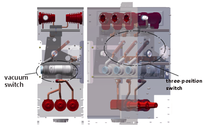
Saboda vacuum switch yana ƙoƙarin a cikin pole, ƙarfin rarrabe ta yana ƙara da epoxy resin. Ƙarfinsa na epoxy resin yana ƙarin da ƙarfinsa na air, saboda haka, ana iya ƙara ƙarfinsa. Da ɗaya, connecting busbar a ƙarfin mai sarrafa solid-insulated pole yana da round corners, curved designs, da kuma silicone rubber sealing, wanda ke ƙara ƙaramin partial discharge a cikin wannan makaranta. Ƙarfinsa a cikin busbars da ground yana da ƙarfin da aka ƙara a cikin tsari mai ƙarfinsa da kuma ƙarfin da aka ƙara.
Isolating blade na three-position switch yana ƙara ƙarfinsa ta hanyar gas air. Idan ake ƙara, tsarin tashin tsafta yana da pins, springs, disc springs, da retaining rings don ƙara pressure a cikin isolating contacts. Amma, saboda tsarin tsafta masu daɗi, suna iya haɗa da sadarwa na electric field da ke ƙarƙashin, wanda ke ƙara ƙaramin partial discharge. Wannan yana haɗa da risk of breakdown discharge, wanda ke ƙara ƙarfinsa a cikin wannan makaranta. Saboda haka, tsarin tashin tsafta a cikin wannan makaranta yana da muhimmanci.
Idan a tabbatar da tushen product design, isolating gap yana da muhimmanci a yi ƙarfin da take da rated short-time power-frequency withstand voltage na 50kV. Ƙarfinsa na electrical clearance na isolating gap yana ƙara da 100mm. Saboda tsarin tsafta na isolating blade, an saka grading shields a duk biyu na isolating blade don ƙara tsari na electric field da kuma ƙara ƙaramin partial discharge. Model na 3D na three-position switch yana nuna a Fig. 2. Saboda haka, littafin ɗin yana yi simulation analysis na electric field na isolating gap.
An amfani da software na finite element don yi simulation na electric field na RMU, yana bin samun distribution na electric field intensity a cikin isolating gap a cikin 50kV rated short-time power-frequency withstand voltage. An bayyana wasu ɗaya daga cikin scenarios na electrostatic field:
An samu distribution na electric field a cikin isolating gap a cikin ɗuka scenarios daga simulation. Distribution na electric field intensity a cikin isolating blade head a Scenario 1 yana nuna a Fig. 3, da kuma a cikin isolating static contact seat a Scenario 2 yana nuna a Fig. 4. Maximum electric field intensity a Scenario 1 yana ƙara a ƙarfin grading shield, da ƙarfin 7.07 kV/mm. Maximum a Scenario 2 yana ƙara a chamfer na isolating static contact seat, da ƙarfin 4.90 kV/mm.
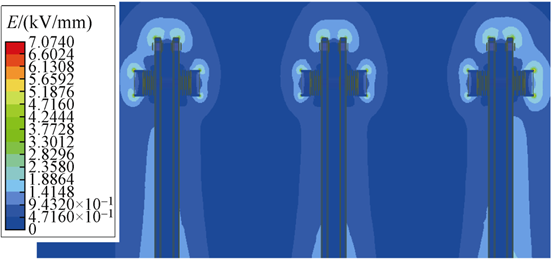
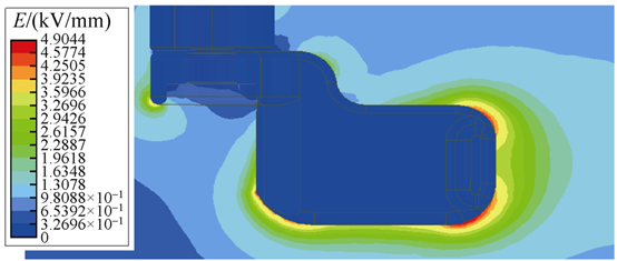
Critical breakdown electric field strength na air a cikin standard conditions yana ƙarfin da 3 kV/mm. Fig. 3 da Fig. 4 sun nuna cewa lokacin da some areas a cikin isolating gap suka ƙarfin 3 kV/mm, ƙarfin a wasu areas suka ƙara da ƙarfin, saboda haka, breakdown discharge ba zai faru ba. Amma, partial discharge zai faru a cikin localized positions idan ƙarfin suka ƙarfin 3 kV/mm.
Idan air yana ƙara da dry zuwa humid, ƙarfinsa yana ƙara. Critical breakdown electric field strength a cikin uniform field conditions yana ƙara da 3 kV/mm. Da ɗaya, extremely non-uniform electric field distribution yana ƙara ƙarfinsa. Duk ɗaya suna ƙara risk of breakdown. Don ƙara impact of external environmental conditions a cikin air insulation medium da kuma ƙara coefficient of electric field, littafin ɗin yana nuna degree of uniformity na electric field a cikin isolating gap da kuma withstand voltage value na gap. Wannan yana ƙara basis for enhancing ƙarfinsa na isolating gap.
3 Air Insulation Characteristics
3.1 Determination of Electric Field Non-Uniformity Coefficient
Perfectly uniform electric fields ba su kaɗa a cikin ƙasashe, duka electric fields su ƙarƙashin. Based on the non-uniformity coefficient f, electric fields are classified into two types: slightly non-uniform electric fields when f ≤ 4; and extremely non-uniform electric fields when f > 4. The electric field non-uniformity coefficient f is determined by f = E_max / E_avg, where E_max is the local maximum electric field strength, obtainable from simulation results, and E_avg is the average electric field strength, calculated as the applied voltage divided by the minimum electrical clearance.
From Fig. 3, E_max = 7.07 kV/mm and E_avg = 0.5 kV/mm (50kV / 100mm). Therefore, the non-uniformity coefficient for the isolating gap f = 14.14 > 4, classifying it as an extremely non-uniform field. Stable partial discharge phenomena can form near extremely non-uniform fields. The greater the degree of non-uniformity, the more pronounced the partial discharge, and the larger the discharge magnitude. For a 12kV RMU, the requirement is that the total partial discharge of the entire cabinet should be less than 20pC. Reducing the non-uniformity coefficient f is beneficial for decreasing partial discharge magnitude.
3.2 Determination of Air Withstand Voltage
The non-uniformity coefficient affects the withstand voltage of dry air. When the field is slightly non-uniform, the withstand voltage is:
Formula (1)
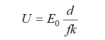
Where:
From Formula (1), increasing the minimum electrical clearance d or decreasing the non-uniformity coefficient f can improve the air's withstand voltage. When the field is extremely non-uniform, for electrodes with a minimum clearance d around 100mm, the withstand voltage is determined by:
Formula (2)
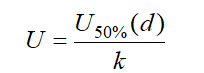
Where is the lightning impulse 50% breakdown voltage for the electrode with an electrical clearance of d. In extremely non-uniform fields, breakdown voltage exhibits significant dispersion and a long discharge time delay, making it highly unstable.
In engineering practice, U<sub>50%(d)</sub> is determined through multiple lightning impulse tests: the applied voltage at which breakdown occurs with a 50% probability is defined as U<sub>50%(d)</sub>. This value depends on the product structure and the degree of field uniformity. It is established that a lower non-uniformity coefficient results in smaller breakdown voltage dispersion, higher breakdown voltage, and consequently, a higher withstand voltage. Therefore, reducing the non-uniformity coefficient f improves the withstand voltage of the isolating gap.
4 Structural Optimization
To improve the uniformity of the electric field around the isolating blade head and reduce the non-uniformity coefficient, the grading shield structure was optimized.
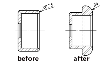
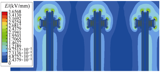
Compared to the original design, the optimized grading shield features a thickened end with a rounded corner design. The fillet radius was increased from 0.75mm to 4mm, enhancing the curvature radius in this area, which benefits achieving more uniform field distribution. The electric field intensity distribution at the optimized isolating blade head is shown in Fig. 7. The figure shows the maximum electric field intensity at this location is now 3.66 kV/mm, approximately half of the value before optimization, indicating significant improvement.
Based on the formula f = E_max / E_avg, the electric field non-uniformity coefficient after optimization is 7.32. Compared to the pre-optimization state, this value is reduced to about half. The uniformity of the electric field near the isolating blade head has also significantly improved, demonstrating the reasonableness of the structural optimization.
The optimized grading shield structure indeed reduces the risk of breakdown discharge across the isolating gap. However, the electric field across the gap remains extremely non-uniform, and its withstand voltage is still determined by U<sub>50%(d)</sub>. The extent to which the withstand voltage can be increased needs to be determined through subsequent field tests.
5 Conclusion
Through electric field analysis of the isolating gap in a 12kV air-insulated RMU, this paper reached the following conclusions: