Da qāwrang-e tārīqi-ye narkh kār bārānaw, pāydā kardan-e mafhūm-e kārgāh-e kāmik, energi-bārānaw, da orzmiyānaw tā biškār da grawestay jadwal wa ṣanʿat rawānaw-e barq awerist rawi. Ring Main Unit (RMU) yake cihaz-e elektriki-muhim da tāriqe-e barq-dān. Da amniyat, orzmiyānaw, da peyāwandiggar, energezi, da ekonomi yake tāriqe-e mustaqill dā rawi. RMU-hā-ye matali da SF6 gas-insulated RMU-hā. Tārānāwa SF6 da kapasite-ye zyādat-e arq-e xātir wā da insulāsione-ye zyād, yake āmāl-e melāna. Lačin, SF6 da orzmiyānaw-e ghāb-e zyād. Da rābari-e ziādat-e qānuni bar ghāb-e zyād, da awerist rawi-e RMU-hā-ye gas-insulated-e orzmiyānaw ba alternativ-e SF6.
Da hāl, RMU-hā-ye gas-insulated-e orzmiyānaw da nitrogen-insulated RMU-hā da dry air-insulated RMU-hā. Literatur da awerist rawi-e še. Taṭbiq ba kapasite-ye insulāsione-ye SF6, da nitrogen da dry air da yake zyārat-e yek-she'ār. Lačin, da ta'min-e ke kapasite-ye insulāsione-ye umumiy-e RMU da switche-ye dahāne-ye he not be kām-e taḥt-e kapasite-ye insulāsione-ye medium, da ḥifẓ-e mekan-e kāfe, yake muhim. Da ta'thir-e taḥt-e tāriqe-ye tahāwil-e elektriki da insulāsione. Tahāwil-e elektriki da insulāsione-e wāqe'e da taḥlil-e kam-e kapasite-ye medium.
Da maqala da isolating gap-e yake 12kV air-insulated RMU. Da tahlil-e electric field distribution-e naqdi da uniformity, da tashih-e kapasite-ye insulāsione-e naqdi, da tajdid-e strukturi ba ḥefz-e imkān-e discharge da tashih-e kapasite-ye insulāsione. Da maqsad-e tashih-e insulāsione-e mahsolāt-e mithli.
1 Struktur-e Air-Insulated RMU
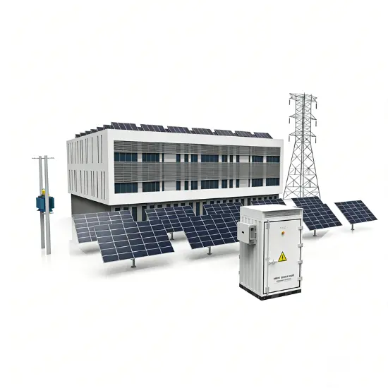
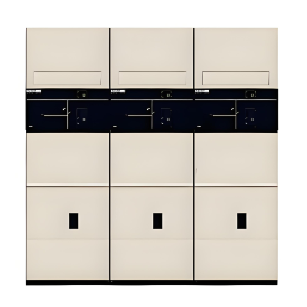
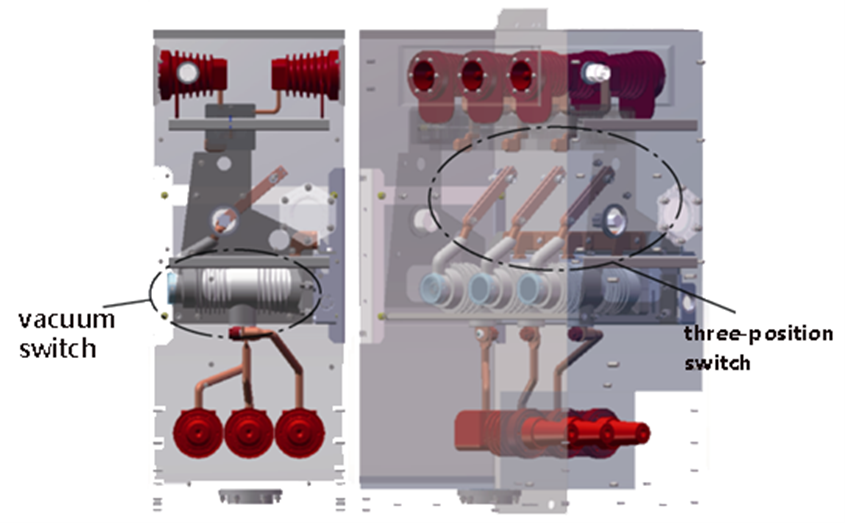
Da model-e 3D-e struktur-e air-insulated RMU-e maqal-e hāl da Figure 1. Da struktur-e main circuit-e RMU da tāriqe-ye combini-e switch-e vacuum da three-position switch. Da layout da tāriqe-ye three-position switch-e busbar side, yani, da three-position switch-e upper side-e RMU, da switch-e vacuum-e lower side-e solid-insulated pole.
Pas switch-e vacuum-e pole, da exterior-e insulāsione-e epoxy resin. Da kapasite-ye insulāsione-ye epoxy resin da zyād-e air, ta taḥlil-e insulāsione. Da connecting busbar-e sealed end-e solid-insulated pole da rounded corners, curved designs, da silicone rubber sealing, da partial discharge-e naqdi. Da insulāsione clearance-e bayn-e busbars da to the ground da tāriqe-e insulāsione requirements da regulations.
Da isolating blade-e three-position switch da insulāsione-e air. Da tāriqe-e connecting-e movable, da struktur-e tāriqe-e metal parts-e pins, springs, disc springs, da retaining rings da tashih-e contact pressure-e bayn-e isolating contacts. Lačin, da shapes-e special-e metal parts, da electric field distribution-e highly non-uniform, da partial discharge. Da risk-e breakdown discharge, da kapasite-ye insulāsione-e naqdi. Da tāriqe-e tahāwil-e elektriki da muhim.
Ta product design requirements, da isolating gap da tāq-e rated short-time power-frequency withstand voltage-e 50kV. Da minimum electrical clearance-e isolating gap da tāq-e 100mm. Da complexity-e struktur-e isolating blade, da grading shields-e added-e both sides-e isolating blade da tashih-e electric field uniformity da reduce-e partial discharge. Da 3D model-e three-position switch da Figure 2. Da maqala da tahlil-e electric field simulation-e isolating gap.
Finite element software da simulate-e electric field-e RMU, da tahlil-e electric field intensity distribution-e bayn-e isolating gap-e under-e 50kV rated short-time power-frequency withstand voltage. Two scenarios-e electrostatic field simulation-e defined:
Da electric field distributions-e location-e maximum electric field intensity-e bayn-e isolating gap-e both scenarios-e obtained-e simulation. Da electric field intensity distribution-e isolating blade head-e Scenario 1 da Figure 3, da isolating static contact seat-e Scenario 2 da Figure 4. Da maximum electric field intensity-e Scenario 1 da end-e grading shield, measuring 7.07 kV/mm. Da maximum-e Scenario 2 da chamfer-e isolating static contact seat, measuring 4.90 kV/mm.
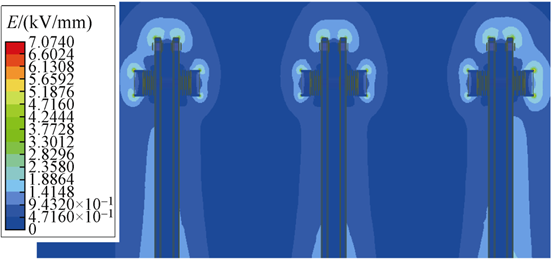
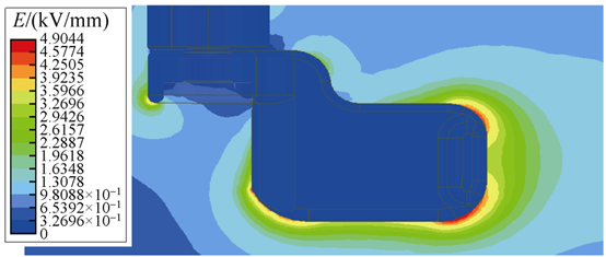
Da critical breakdown electric field strength-e air-e standard conditions da 3 kV/mm. Figures 3 da 4 da localized areas-e bayn-e isolating gap-e exceed-e 3 kV/mm, da field intensity-e other areas-e below-e threshold, da breakdown discharge-e unlikely. Lačin, da partial discharge-e localized positions-e field strength-e exceed-e 3 kV/mm.
Da air-e change-e dry-e humid, da kapasite-ye insulāsione-e decrease. Da critical breakdown electric field strength-e uniform field conditions-e fall-e below-e 3 kV/mm. Da extremely non-uniform electric field distribution-e also-e lowers-e air's critical breakdown field strength. Both factors-e increase-e possibility da risk-e breakdown. Da mitigate-e impact-e external environmental conditions-e air insulation medium da tashih-e uniformity coefficient-e electric field, da maqala da tāmin-e degree-e uniformity-e electric field-e bayn-e isolating gap da withstand voltage value-e gap. Da basis-e tashih-e kapasite-ye insulāsione-e isolating gap.
3 Air Insulation Characteristics
3.1 Determination-e Electric Field Non-Uniformity Coefficient
Perfectly uniform electric fields-e exist-e practice, all electric fields-e non-uniform. Ta non-uniformity coefficient f, electric fields-e classified-e two types: slightly non-uniform electric fields-e f ≤ 4; da extremely non-uniform electric fields-e f > 4. Da electric field non-uniformity coefficient f da determined-e f = E_max / E_avg, da E_max da local maximum electric field strength, obtainable-e simulation results, da E_avg da average electric field strength, calculated-e applied voltage divided-e minimum electrical clearance.
Da Figure 3, E_max = 7.07 kV/mm da E_avg = 0.5 kV/mm (50kV / 100mm). Therefore, da non-uniformity coefficient-e isolating gap f = 14.14 > 4, classifying-e extremely non-uniform field. Stable partial discharge phenomena-e form-e near-e extremely non-uniform fields. Da greater-e degree-e non-uniformity, da more pronounced-e partial discharge, da larger-e discharge magnitude. Da 12kV RMU, da requirement-e total partial discharge-e entire cabinet-e less-e 20pC. Reducing-e non-uniformity coefficient f da beneficial-e decreasing-e partial discharge magnitude.
3.2 Determination-e Air Withstand Voltage
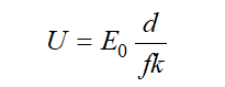
Da non-uniformity coefficient-e affect-e withstand voltage-e dry air. Da field-e slightly non-uniform, da withstand voltage-e:
Formula (1)
Where:
Da Formula (1), increasing-e minimum electrical clearance d da decreasing-e non-uniformity coefficient f da improve-e air's withstand voltage. Da field-e extremely non-uniform, da electrodes-e minimum clearance d around-e 100mm, da withstand voltage-e determined-e:
Formula (2)
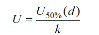
Where da lightning impulse 50% breakdown voltage-e electrode-e electrical clearance-e d. Da extremely non-uniform fields, da breakdown voltage-e exhibit-e significant dispersion da long discharge time delay, da highly unstable.
Da engineering practice, U<sub>50%(d)</sub> da determined-e multiple lightning impulse tests: da applied voltage-e which-e breakdown-e 50% probability da defined-e U<sub>50%(d)</sub>. Da value-e depend-e product structure da degree-e field uniformity. Da established-e lower non-uniformity coefficient-e result-e smaller breakdown voltage dispersion, higher breakdown voltage, da consequently, da higher withstand voltage. Da reducing-e non-uniformity coefficient f da improve-e withstand voltage-e isolating gap.
4 Structural Optimization
Da improve-e uniformity-e electric field-e around-e isolating blade head da reduce-e non-uniformity coefficient, da grading shield structure-e optimized.
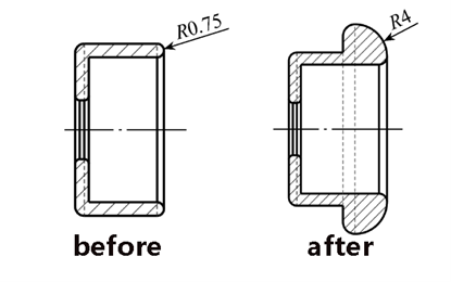
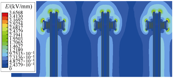
Compared-e original design, da optimized grading shield-e thickened end-e rounded corner design. Da fillet radius-e increased-e 0.75mm da 4mm, enhancing-e curvature radius-e area, da benefits-e achieving-e more uniform field distribution. Da electric field intensity distribution-e optimized isolating blade head-e Figure 7. Da figure-e maximum electric field intensity-e location-e now-e 3.66 kV/mm, approximately half-e value-e before optimization, indicating-e significant improvement.
Based-e formula f = E_max / E_avg, da electric field non-uniformity coefficient-e after optimization-e 7.32. Compared-e pre-optimization state, da value-e reduced-e about half. Da uniformity-e electric field-e near-e isolating blade head-e also-e significantly improved, demonstrating-e reasonableness-e structural optimization.
Da optimized grading shield structure-e indeed-e reduces-e risk-e breakdown discharge-e bayn-e isolating gap. Lačin, da electric field-e bayn-e gap-e still-e extremely non-uniform, da withstand voltage-e still-e determined-e U<sub>50%(d)</sub>. Da extent-e which-e withstand voltage-e can-e increased-e needs-e determined-e subsequent field tests.
5 Conclusion
Da electric field analysis-e isolating gap-e 12kV air-insulated RMU, da maqala-e reached-e following conclusions: