With the rapid development of the power industry, the ecological concept of low-carbon, energy-saving, and environmental protection has been deeply integrated into the design and manufacturing of power supply and distribution electrical products. The Ring Main Unit (RMU) is a key electrical device in distribution networks. Safety, environmental protection, operational reliability, energy efficiency, and economy are inevitable trends in its development. Traditional RMUs are primarily represented by SF6 gas-insulated RMUs. Due to SF6's excellent arc-extinguishing capability and high insulation performance, they have been widely used. However, SF6 causes the greenhouse effect. With increasing regulatory pressure on greenhouse gases, developing environmentally friendly gas-insulated RMUs as alternatives to SF6 has become an imperative trend.
Currently, environmentally friendly gas-insulated RMUs include nitrogen-insulated RMUs and dry air-insulated RMUs. Literature has introduced these options. Compared to SF6's insulation capability, that of nitrogen and dry air is only about one-third. Therefore, ensuring that the overall insulation performance of the RMU and its internal switches is not compromised due to the reduced insulation performance of the medium, while maintaining the existing cabinet space, is particularly crucial. This is mainly reflected in the design of the internal electrical structure and insulation structure. Reasonable electrical and insulation structure design can compensate for the deficiency of the insulation medium's performance.
This paper focuses on an isolating gap within a certain 12kV air-insulated RMU. It analyzes the nearby electric field distribution and its uniformity, assesses the insulation performance at this location, and conducts structural optimization to reduce the probability of discharge and improve insulation performance. The study aims to provide a reference for the insulation design of similar products.
1 Structure of the Air-Insulated RMU
The 3D structural model of the air-insulated RMU studied in this paper is shown in Figure 1. The main circuit structure of the RMU adopts a scheme combining a vacuum switch and a three-position switch. The layout employs a scheme where the three-position switch is located on the busbar side, i.e., the three-position switch is arranged on the upper side of the RMU, while the vacuum switch is arranged on the lower side via a solid-insulated pole.
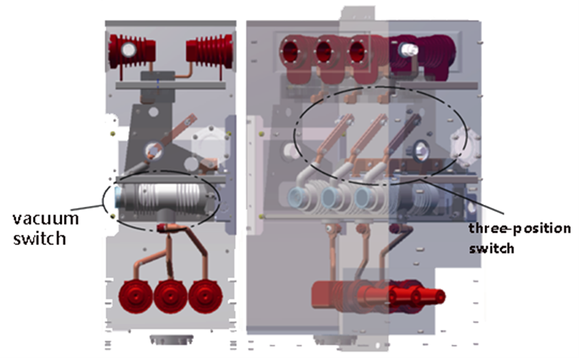
Since the vacuum switch is encapsulated within the pole, its exterior is insulated by epoxy resin. The insulation capability of epoxy resin is far superior to that of air, thus meeting insulation requirements. Furthermore, the connecting busbar at the sealed end of the solid-insulated pole incorporates rounded corners, curved designs, and silicone rubber sealing, resolving partial discharge issues at this point. The insulation clearances between busbars and to the ground are designed according to relevant insulation requirements and comply with regulations.
The isolating blade of the three-position switch relies entirely on the air medium for insulation. As a movable connecting component, its structural design incorporates metal parts such as pins, springs, disc springs, and retaining rings to enhance the contact pressure between isolating contacts. However, due to the special shapes of these metal parts, they can cause highly non-uniform electric field distribution, triggering partial discharge. This poses a risk of breakdown discharge, adversely affecting the insulation performance at this location. Therefore, the electrical structure design here is particularly important.
According to product design requirements, the isolating gap must withstand a rated short-time power-frequency withstand voltage of 50kV. The minimum electrical clearance for the isolating gap is designed as 100mm. Considering the complexity of the isolating blade structure, grading shields were added on both sides of the isolating blade to improve electric field uniformity and reduce the occurrence of partial discharge. The 3D model of the three-position switch is shown in Figure 2. Accordingly, this paper conducts electric field simulation analysis on the isolating gap.
Finite element software was used to simulate the electric field of the RMU, analyzing the electric field intensity distribution across the isolating gap under the given 50kV rated short-time power-frequency withstand voltage. Two scenarios for electrostatic field simulation were defined:
Scenario 1: Busbar side (side with the isolating static contact seat) connected to low potential (0V), line side (side with the isolating blade head) connected to high potential (50kV).
Scenario 2: Busbar side (side with the isolating static contact seat) connected to high potential (50kV), line side (side with the isolating blade head) connected to low potential (0V).
The electric field distributions at the location of maximum electric field intensity within the isolating gap for both scenarios were obtained from the simulation. The electric field intensity distribution at the isolating blade head for Scenario 1 is shown in Figure 3, and that at the isolating static contact seat for Scenario 2 is shown in Figure 4. The maximum electric field intensity in Scenario 1 occurs at the end of the grading shield, measuring 7.07 kV/mm. The maximum in Scenario 2 is at the chamfer of the isolating static contact seat, measuring 4.90 kV/mm.
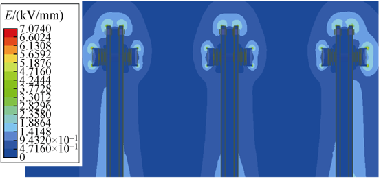
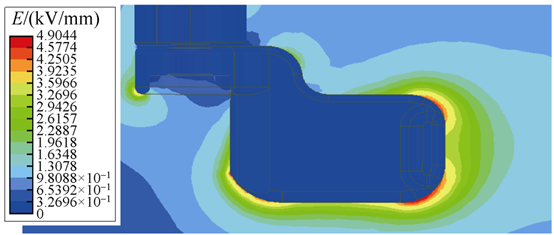
The critical breakdown electric field strength for air under standard conditions is generally 3 kV/mm. Figures 3 and 4 show that while localized areas within the isolating gap exceed 3 kV/mm, the field intensity in other areas remains below this threshold, making breakdown discharge unlikely. However, partial discharge will occur in the localized positions where the field strength exceeds 3 kV/mm.
When air changes from dry to humid, its insulation capability decreases. The critical breakdown electric field strength under uniform field conditions falls below 3 kV/mm. Moreover, extremely non-uniform electric field distribution also lowers air's critical breakdown field strength. Both factors increase the possibility and risk of breakdown. To mitigate the impact of external environmental conditions on the air insulation medium and improve the uniformity coefficient of the electric field, this paper aims to determine the degree of uniformity of the electric field across the isolating gap and the withstand voltage value of the gap. This serves as the basis for enhancing the insulation capability of the isolating gap.
3 Air Insulation Characteristics
3.1 Determination of Electric Field Non-Uniformity Coefficient
Perfectly uniform electric fields do not exist in practice; all electric fields are non-uniform. Based on the non-uniformity coefficient f, electric fields are classified into two types: slightly non-uniform electric fields when f ≤ 4; and extremely non-uniform electric fields when f > 4. The electric field non-uniformity coefficient f is determined by f = E_max / E_avg, where E_max is the local maximum electric field strength, obtainable from simulation results, and E_avg is the average electric field strength, calculated as the applied voltage divided by the minimum electrical clearance.
From Figure 3, E_max = 7.07 kV/mm and E_avg = 0.5 kV/mm (50kV / 100mm). Therefore, the non-uniformity coefficient for the isolating gap f = 14.14 > 4, classifying it as an extremely non-uniform field. Stable partial discharge phenomena can form near extremely non-uniform fields. The greater the degree of non-uniformity, the more pronounced the partial discharge, and the larger the discharge magnitude. For a 12kV RMU, the requirement is that the total partial discharge of the entire cabinet should be less than 20pC. Reducing the non-uniformity coefficient f is beneficial for decreasing partial discharge magnitude.
3.2 Determination of Air Withstand Voltage
The non-uniformity coefficient affects the withstand voltage of dry air. When the field is slightly non-uniform, the withstand voltage is:
Formula (1)
 Where:
U is the withstand voltage.
d is the minimum electrical clearance between electrodes.
k is a reliability factor, typically ranging from 1.2 to 1.5 based on experience.
E₀ is the gas breakdown electric field strength. In practice, this value relates to the electrode structure. The air breakdown field strength varies under different electrode structures and clearances. For comparative analysis in this paper, E₀ = 3 kV/mm is tentatively set.
From Formula (1), increasing the minimum electrical clearance d or decreasing the non-uniformity coefficient f can improve the air's withstand voltage. When the field is extremely non-uniform, for electrodes with a minimum clearance d around 100mm, the withstand voltage is determined by:
Formula (2)

Where is the lightning impulse 50% breakdown voltage for the electrode with an electrical clearance of d. In extremely non-uniform fields, breakdown voltage exhibits significant dispersion and a long discharge time delay, making it highly unstable.
In engineering practice, U<sub>50%(d)</sub> is determined through multiple lightning impulse tests: the applied voltage at which breakdown occurs with a 50% probability is defined as U<sub>50%(d)</sub>. This value depends on the product structure and the degree of field uniformity. It is established that a lower non-uniformity coefficient results in smaller breakdown voltage dispersion, higher breakdown voltage, and consequently, a higher withstand voltage. Therefore, reducing the non-uniformity coefficient f improves the withstand voltage of the isolating gap.
4 Structural Optimization
To improve the uniformity of the electric field around the isolating blade head and reduce the non-uniformity coefficient, the grading shield structure was optimized.
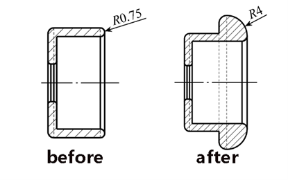
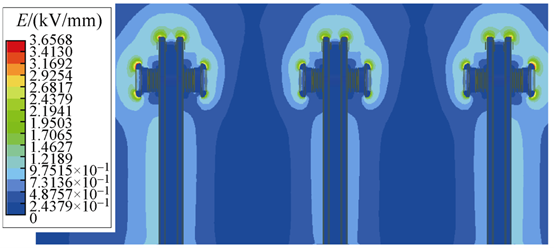
Compared to the original design, the optimized grading shield features a thickened end with a rounded corner design. The fillet radius was increased from 0.75mm to 4mm, enhancing the curvature radius in this area, which benefits achieving more uniform field distribution. The electric field intensity distribution at the optimized isolating blade head is shown in Figure 7. The figure shows the maximum electric field intensity at this location is now 3.66 kV/mm, approximately half of the value before optimization, indicating significant improvement.
Based on the formula f = E_max / E_avg, the electric field non-uniformity coefficient after optimization is 7.32. Compared to the pre-optimization state, this value is reduced to about half. The uniformity of the electric field near the isolating blade head has also significantly improved, demonstrating the reasonableness of the structural optimization.
The optimized grading shield structure indeed reduces the risk of breakdown discharge across the isolating gap. However, the electric field across the gap remains extremely non-uniform, and its withstand voltage is still determined by U<sub>50%(d)</sub>. The extent to which the withstand voltage can be increased needs to be determined through subsequent field tests.
5 Conclusion
Through electric field analysis of the isolating gap in a 12kV air-insulated RMU, this paper reached the following conclusions:
Due to the inferior insulation capability of air compared to SF6, using air for insulation in the three-position switch within RMUs requires improving electric field distribution to enhance insulation capability.
Due to the structural complexity of moving parts (the isolating blade) within the three-position switch of air-insulated RMUs, the electric field intensity distribution at localized positions can become highly non-uniform. To reduce non-uniformity, grading shields can be added on both sides of the isolating blade to shield the electric field intensity near the ends of the blade connectors, shifting the maximum local field intensity to the ends of the grading shields. This paper increased the curvature radius of the grading shield end from 0.75mm to 4mm. This reduced both the maximum local electric field intensity and the non-uniformity coefficient to approximately half their original values, achieving the desired effect.
The degree of electric field uniformity, or the non-uniformity coefficient, significantly impacts partial discharge and breakdown discharge. Extremely non-uniform fields easily lead to stable partial discharge (corona discharge). For both slightly and extremely non-uniform fields, a higher non-uniformity coefficient corresponds to a lower withstand voltage between the two electrodes.


