• Product
  • Suppliers
  • Manufacturers
  • Solutions
  • Free tools
  • Knowledges
  • Experts
  • Communities
Search


High-Current Current-Limiting Circuit Breaker/Short-Circuit Current Limiter(FCL)

  • High-Current Current-Limiting Circuit Breaker/Short-Circuit Current Limiter(FCL)

Key attributes

Brand RW Energy
Model NO. High-Current Current-Limiting Circuit Breaker/Short-Circuit Current Limiter(FCL)
Rated voltage 20kV
Rated normal current 1250A
Rated frequency 50/60Hz
Series DDXK

Product descriptions from the supplier

Description

Product Introduction

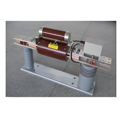
A core protection component for high-capacity power systems (35kV-220kV grids, industrial parks), the FCL responds in ≤10ms to short-circuit faults. It limits peak fault current to 15%-50% of the expected value before safe breaking, shielding generators/transformers. Supporting 630A-4000A current ratings, it fits AC/DC systems and integrates with switchgear for stable grid operation.

Feature

  • High-Speed Interruption: It operates and interrupts the short-circuit current at the front part of the first power frequency half-cycle of the short-circuit current—well before the current rises to its peak. The total interruption time is 2–5 ms, approximately 10–20 times faster than that of conventional circuit breakers.

  • Current-Limiting Interruption: It starts limiting the short-circuit current 1 ms after a short-circuit occurs, and finally restricts the short-circuit current to 15%–45% of the expected value.

  • High Interruption Capacity: The rated prospective short-circuit interruption current ranges from 63 kA to 200 kA, while the rated short-circuit interruption current of currently common circuit breakers usually only reaches 40.5 kA to 50 kA.

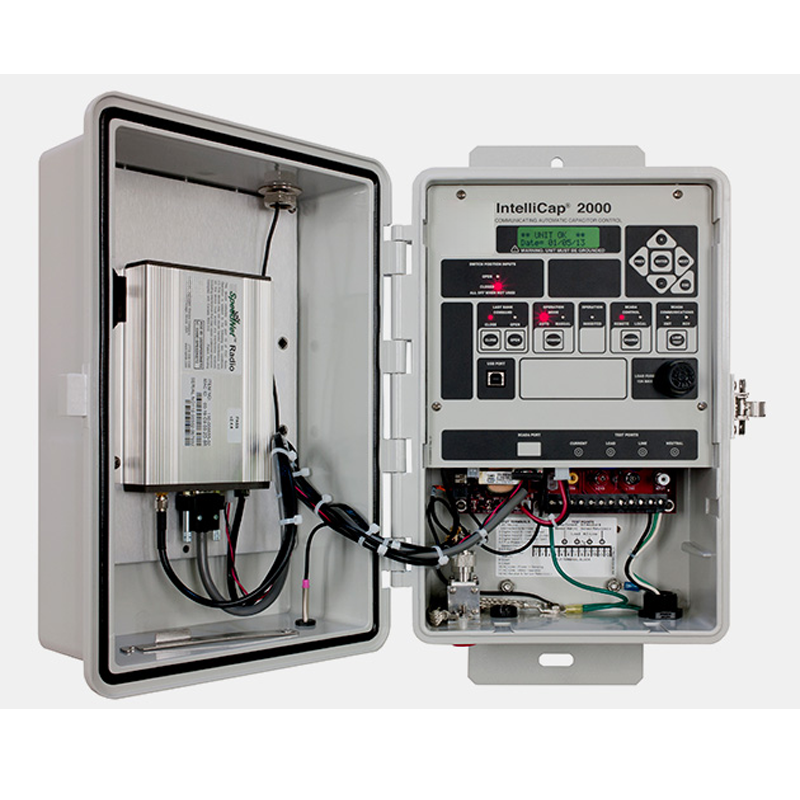
  • Built-in Rogowski Current Sensor: It features accurate measurement, fast response speed, and can be arranged in a phase-separated manner or integrated into switchgear cabinets.

  • High Reliability: One of the product’s competitive advantages is its outstanding reliability. Special design and craftsmanship ensure the product’s high reliability, which has been verified and well-received in on-site applications.

Main Parameters

No.

Item


Unit

Technical Parameters

1

Rated Current

A

630~6300

2

Rated Voltage

kV

7.2/12/20/40.5

3

Rated Frequency

Hz

50/60

4

Rated Prospective Short - Circuit Breaking Current

kA

63/80/120

5

Rated Insulation Level (Power Frequency / Lightning)

7.2kV

kV

 23/60 kV

12kV

42/75 kV

20kV

50/125 kV

40.5kV

95/185 kV

6

Breaking Time


ms

2~5ms

7

Cut - off Current / Prospective Short - Circuit Current Peak Value

%

20~45

8

DC Resistance of Main Circuit

μΩ

<40

9

Operating Current Setting Range

kA

6kA~60kA

10

Rated Breaking Current of Fuse

kA

63/120

11

Rated Short - time Withstand Current of Main Circuit

kA/s

31.5/2

12

Rated Peak Withstand Current of Main Circuit

kA

80

Figure 4: Using DDXK1 as rapid short-circuit protection for generators and transformers
(a) Rapid short-circuit protection at the 10kV/35kV side outlet of transformers
(b) Rapid short-circuit protection at generator outlets
(c) Rapid short-circuit protection for power plant branch busbars
(d) Rapid short-circuit protection at grid-connected generator outlets

Know your supplier
Online store
On-time delivery rate
Response time
100.0%
≤4h
Company overview
Workplace: 30000m² Total staff: Highest Annual Export(usD): 100000000
Workplace: 30000m²
Total staff:
Highest Annual Export(usD): 100000000
Services
Business Type: Design/Manufacture/Sales
Main Categories: High Voltage Electrical Apparatus/Low Voltage Electrical Apparatus/Instrument meters/New energy/Tester/Robot
Whole life care manager
Whole-life care management services for equipment procurement, use, maintenance, and after-sales, ensuring safe operation of electrical equipment, continuous control, and worry-free electricity consumption.
The equipment supplier has passed platform qualification certification and technical evaluation, ensuring compliance, professionalism, and reliability from the source.

Related Products

Related Knowledges

  • Impact of DC Bias in Transformers at Renewable Energy Stations Near UHVDC Grounding Electrodes
    Impact of DC Bias in Transformers at Renewable Energy Stations Near UHVDC Grounding ElectrodesWhen the grounding electrode of an Ultra-High-Voltage Direct Current (UHVDC) transmission system is located close to a renewable energy power station, the return current flowing through the earth can cause a rise in ground potential around the electrode area. This ground potential rise leads to a shift in the neutral-point potential of nearby power transformers, inducing DC bias (or DC offset) in their
    01/15/2026
  • HECI GCB for Generators – Fast SF6 Circuit Breaker
    1.Definition and Function1.1 Role of the Generator Circuit BreakerThe Generator Circuit Breaker (GCB) is a controllable disconnect point located between the generator and the step-up transformer, serving as an interface between the generator and the power grid. Its primary functions include isolating generator-side faults and enabling operational control during generator synchronization and grid connection. The operating principle of a GCB is not significantly different from that of a standard c
    01/06/2026
  • Distribution Equipment Transformer Testing, Inspection, and Maintenance
    1.Transformer Maintenance and Inspection Open the low-voltage (LV) circuit breaker of the transformer under maintenance, remove the control power fuse, and hang a “Do Not Close” warning sign on the switch handle. Open the high-voltage (HV) circuit breaker of the transformer under maintenance, close the grounding switch, fully discharge the transformer, lock the HV switchgear, and hang a “Do Not Close” warning sign on the switch handle. For dry-type transformer maintenance: first clean the porcel
    12/25/2025
  • How to Test Insulation Resistance of Distribution Transformers
    In practical work, insulation resistance of distribution transformers is generally measured twice: the insulation resistance between thehigh-voltage (HV) windingand thelow-voltage (LV) winding plus the transformer tank, and the insulation resistance between theLV windingand theHV winding plus the transformer tank.If both measurements yield acceptable values, it indicates that the insulation among the HV winding, LV winding, and transformer tank is qualified. If either measurement fails, pairwise
    12/25/2025
  • Design Principles for Pole-Mounted Distribution Transformers
    Design Principles for Pole-Mounted Distribution Transformers(1) Location and Layout PrinciplesPole-mounted transformer platforms should be located near the load center or close to critical loads, following the principle of “small capacity, multiple locations” to facilitate equipment replacement and maintenance. For residential power supply, three-phase transformers may be installed nearby based on current demand and future growth projections.(2) Capacity Selection for Three-Phase Pole-Mounted Tr
    12/25/2025
  • Transformer Noise Control Solutions for Different Installations
    1.Noise Mitigation for Ground-Level Independent Transformer RoomsMitigation Strategy:First, conduct a power-off inspection and maintenance of the transformer, including replacing aged insulating oil, checking and tightening all fasteners, and cleaning dust from the unit.Second, reinforce the transformer foundation or install vibration isolation devices—such as rubber pads or spring isolators—selected based on the severity of vibration.Finally, strengthen sound insulation at weak points of the ro
    12/25/2025

Related Solutions

  • Distribution automation systems solutions
    What are the difficulties in overhead line operation and maintenance?Difficulty one:Overhead lines of distribution network have wide coverage,complicatedterrain,many radiation branches and distributed power supply,resultingin "many line faults and difficulty in fault troubleshooting".Difficulty Two:Manual troubleshooting is time-consuming and laborious.Meanwhile,therunning current,voltage and switching state of the line cannot be graspedin real time,because of the lack of intelligent technical m
    04/22/2025
  • RW8000 DMS Distribution Management System Solutions
    OverviewNowadays, the development trend of power grid is intellectualization. As an important part of power grid, the power distribution system is very close to the customers and it has to run properly. The distribution management system (DMS)played an important role in it.Introduction:RW8000 power distribution management system (DMS) is designed for the smart grids. It is based on real-time application, centered on distribution network operation and management, focusing on the business process
    09/07/2023
  • High-Precision Electrical Parameter Monitoring System Solution
    1.Introduction​With the increasingly stringent requirements for power supply quality in high-end facilities such as precision manufacturing, medical diagnosis, and data centers, traditional power monitoring systems, due to their low sampling accuracy and weak data analysis capabilities, can no longer meet the demand for deep insight and precise management of power quality. In response, we are introducing a new generation ​High-Precision Electrical Parameter Monitoring System. With ​millisecond-l
    09/28/2025
Haven't found the right supplier yet? Let matching verified suppliers find you. Get Quotation Now
Haven't found the right supplier yet? Let matching verified suppliers find you.
Get Quotation Now
Send inquiry
+86
Click to upload file

IEE Business will not sell or share your personal information.

Download
Get the IEE Business Application
Use the IEE-Business app to find equipment, obtain solutions, connect with experts, and participate in industry collaboration anytime, anywhere—fully supporting the development of your power projects and business.