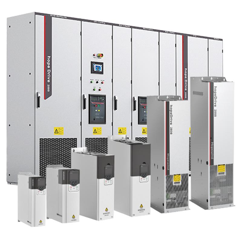
400V/690V 5.5kW~1400kW Low Voltage Engineered Frequency Converter


Key attributes
| Brand | RW Energy |
| Model NO. | 400V/690V 5.5kW~1400kW Low Voltage Engineered Frequency Converter |
| Rated frequency | 50/60Hz |
| Series | HD2000 |
Product descriptions from the supplier
Overview
400V, 690V/5.5kW~1400kW, and the maximum power of the parallel machine can reach 11200kW
Performance characteristics
Engineered reliability design
High redundancy of control system and power system improves overall reliability of the product
Long-life heat dissipation design improves the life of vulnerable components such as fans and capacitors
Innovative large heat capacity radiator improves the ability to adapt to instantaneous strong shock loads
The control system is connected with each power unit using optical fiber to improve the system's anti-interference ability
The heat dissipation channel is isolated from the internal components, which is more conducive to component protection. Improve environmental adaptability
Blocked" design
No special tools required, simple and fast
Modular components for all frontal maintenance
Intelligent fault diagnosis system for quick positioning
Highly adaptable design
Support single-axis drive, multi-axis drive, unit, unit cabinet, two-quadrant, four-quadrant
Complete rectification front-end: basic rectification, intelligent rectification and PWM rectification
Strong grid adaptability, support wide range input to the grid
IEC60721 normal operation of 3M5 mechanical conditions
Precise mechanical design to ensure high seismic resistance
Customizable communication protocols
By selecting different modules, it supports the formulated communication protocol, which can achieve seamless connection with the existing PLC, making it easier to replace and maintain.
Support Profibus-DP, CANopen, Profinet IO, Modbus RTU, Modbus TCP, EtherCAT, EtherNet/IP, ControlNet and DeviceNet for a variety of industrial application buses. Easily realize the interconnection of various industrial equipment
Rich human-computer interaction tools
Configurable powerful LCD keyboard panel for on-site parameter setting, system information display, etc.
HopeInsight background software can be connected to the PC to realize intelligent fault recording, fault diagnosis, etc
Main parameters
project |
Specifications and technical data |
|
Basic rectification |
Input voltage |
4:380V~480V,6:500V~690V |
Input frequency |
(50Hz/60Hz)±6% |
|
Output voltage |
Input Voltage*1.32 (Full Load Condition) |
|
Overload capacity |
Relative base load current IH_DC allows 150% overload for 60s with a maximum current Imax_DC overload 5s, load cycle 300s |
|
Efficiency |
≥99% |
|
Protection function |
Overheating protection, soft rise protection, interlock protection, etc |
|
Intelligent rectification |
Input voltage |
4:380V~480V,6:500V~690V |
Input frequency |
47~63Hz |
|
Output voltage |
Input Voltage*1.3 (Full Load Condition) |
|
Overload capacity |
Relative base load current IH_DC allows 150% overload for 60s with a maximum current Imax_DC overload 5s, load cycle 300s |
|
Efficiency |
≥98.5% |
|
Protection function |
Overheat protection, overcurrent protection, IGBT pass-through protection, etc |
|
PWM rectification |
Input voltage |
4:380V~480V,6:500V~690V,9:1140V,A:1380V |
Input frequency |
47~63Hz |
|
Output voltage |
Input Voltage*1.5 (Rated Condition) |
|
Overload capacity |
Relative base load current IH_DC allows 150% overload for 60s with a maximum current Imax_DC overload 5s, load cycle 300s |
|
Efficiency |
≥98% (including LCL filter unit) |
|
Factor |
Adjustable (factory set to 1) |
|
Protection function |
Over-temperature protection, over-current protection, overload protection, IGBT pass-through protection, etc |
|
Inverse |
Rated input voltage |
4:410Vdc~780Vdc,6:550Vdc~1100Vdc,9:1488Vdc~2200Vdc |
A:1488Vdc~2200Vdc |
||
Output voltage |
0~Rectifier AC input voltage |
|
Output frequency |
0~500Hz |
|
speed regulation range |
V/F:1:50 OLVC:1:200 CLVC:1:1000 |
|
Steady speed accuracy |
OLVC:0.2% ; CLVC:0.01% |
|
Pulsating speed |
OLVC:0.2%; CLVC:0.1% |
|
Start torque |
OLVC:150%(0.5Hz) ; CLVC:200%(0Hz) |
|
Torque control |
V/F: Not supported; OLVC: Support ; CLVC: Yes |
|
Torque accuracy |
OLVC:5% ; CLVC:5% |
|
Torque response time |
OLVC:5ms ; CLVC:5ms |
|
RPM response time |
OLVC:100ms; CLVC:100ms |
|
Dynamic drop equivalent |
OLVC:0.5%*s; CLVC:0.3%*s |
|
environmental conditions |
temperature |
-15°C~+40°C is not degraded, and +40°C~+55°C is degraded |
humidity |
5%~95% non-condensation |
|
elevation |
≤ 4000m, 2000m~4000m reduced use |
|
Mechanical data |
Anti-vibration performance |
Complies with IEC 60721-3-3:2002 |
Protection level |
IP00 / IP20 / IP40 |
|
Safety level |
Meets UL 508C-2004 |
|
Cooling method |
Cold wind, cold water |
|

Related Products
-
30-800kVA 3-Phase AC Power Voltage Stabilizer

-
0~1500Hz High-performance frequency converters

-
0 to 600Hz Special frequency converter for lifting

-
1.65 to 20kV 50/60HZ engineering MV voltage regulation frequency converter

-
400V/690V/1140V/1380V 160kW~2800k Low Voltage Engineered Frequency Converter

-
0 to 500Hz 200V to 690V engineering frequency converter

-
660V mine special frequency converter

Related Knowledges
-
 Impact of DC Bias in Transformers at Renewable Energy Stations Near UHVDC Grounding ElectrodesImpact of DC Bias in Transformers at Renewable Energy Stations Near UHVDC Grounding ElectrodesWhen the grounding electrode of an Ultra-High-Voltage Direct Current (UHVDC) transmission system is located close to a renewable energy power station, the return current flowing through the earth can cause a rise in ground potential around the electrode area. This ground potential rise leads to a shift in the neutral-point potential of nearby power transformers, inducing DC bias (or DC offset) in their01/15/2026
 -
 HECI GCB for Generators – Fast SF6 Circuit Breaker1.Definition and Function1.1 Role of the Generator Circuit BreakerThe Generator Circuit Breaker (GCB) is a controllable disconnect point located between the generator and the step-up transformer, serving as an interface between the generator and the power grid. Its primary functions include isolating generator-side faults and enabling operational control during generator synchronization and grid connection. The operating principle of a GCB is not significantly different from that of a standard c01/06/2026
 -
 Distribution Equipment Transformer Testing, Inspection, and Maintenance1.Transformer Maintenance and Inspection Open the low-voltage (LV) circuit breaker of the transformer under maintenance, remove the control power fuse, and hang a “Do Not Close” warning sign on the switch handle. Open the high-voltage (HV) circuit breaker of the transformer under maintenance, close the grounding switch, fully discharge the transformer, lock the HV switchgear, and hang a “Do Not Close” warning sign on the switch handle. For dry-type transformer maintenance: first clean the porcel12/25/2025
 -
 How to Test Insulation Resistance of Distribution TransformersIn practical work, insulation resistance of distribution transformers is generally measured twice: the insulation resistance between thehigh-voltage (HV) windingand thelow-voltage (LV) winding plus the transformer tank, and the insulation resistance between theLV windingand theHV winding plus the transformer tank.If both measurements yield acceptable values, it indicates that the insulation among the HV winding, LV winding, and transformer tank is qualified. If either measurement fails, pairwise12/25/2025
 -
 Design Principles for Pole-Mounted Distribution TransformersDesign Principles for Pole-Mounted Distribution Transformers(1) Location and Layout PrinciplesPole-mounted transformer platforms should be located near the load center or close to critical loads, following the principle of “small capacity, multiple locations” to facilitate equipment replacement and maintenance. For residential power supply, three-phase transformers may be installed nearby based on current demand and future growth projections.(2) Capacity Selection for Three-Phase Pole-Mounted Tr12/25/2025
 -
 Transformer Noise Control Solutions for Different Installations1.Noise Mitigation for Ground-Level Independent Transformer RoomsMitigation Strategy:First, conduct a power-off inspection and maintenance of the transformer, including replacing aged insulating oil, checking and tightening all fasteners, and cleaning dust from the unit.Second, reinforce the transformer foundation or install vibration isolation devices—such as rubber pads or spring isolators—selected based on the severity of vibration.Finally, strengthen sound insulation at weak points of the ro12/25/2025
Related Solutions
-
 Distribution automation systems solutionsWhat are the difficulties in overhead line operation and maintenance?Difficulty one:Overhead lines of distribution network have wide coverage,complicatedterrain,many radiation branches and distributed power supply,resultingin "many line faults and difficulty in fault troubleshooting".Difficulty Two:Manual troubleshooting is time-consuming and laborious.Meanwhile,therunning current,voltage and switching state of the line cannot be graspedin real time,because of the lack of intelligent technical m04/22/2025
 -
 RW8000 DMS Distribution Management System SolutionsOverviewNowadays, the development trend of power grid is intellectualization. As an important part of power grid, the power distribution system is very close to the customers and it has to run properly. The distribution management system (DMS)played an important role in it.Introduction:RW8000 power distribution management system (DMS) is designed for the smart grids. It is based on real-time application, centered on distribution network operation and management, focusing on the business process09/07/2023
 -
 High-Precision Electrical Parameter Monitoring System Solution1.IntroductionWith the increasingly stringent requirements for power supply quality in high-end facilities such as precision manufacturing, medical diagnosis, and data centers, traditional power monitoring systems, due to their low sampling accuracy and weak data analysis capabilities, can no longer meet the demand for deep insight and precise management of power quality. In response, we are introducing a new generation High-Precision Electrical Parameter Monitoring System. With millisecond-l09/28/2025


