
מצב החיבור הנייטרלי מתייחס לקישור בין נקודת האפס של מערכת החשמל לאדמה. במערכות סיניות של 35 ק"ו ומטה, שיטות נפוצות כוללות חיבור ניוטרלי לא מוקש, חיבור באמצעות סליל כיבוי קשת, וחיבור באמצעות 저נגד קטן. מצב הלא-הצמד הוא בשימוש נרחב מכיוון שהוא מאפשר פעולה קצרת-טווח במהלך תקלות הצמדה חד-פאזה, בעוד שהחיבור באמצעות 저נגד קטן הפך לזרם המרכזי בזכות הסרת התקלה מהירה והגבלת יתר-מתח. מספר תחנות עיקול מתקינות טראנספורמרים צימוד כדי לעדכן את הצמדה נייטרלית, אך שינוי מאפייני התקלה משפיעים על הגנה רלו, עם סיכון למפעילה או דחייה.
מאמר זה מציג עקרונות ומאפיינים של טראנספורמר הצמדה, מתאר את הקונפיגורציה/הגדרת ההגנה הנוכחית במערכות עם 저נגד קטן, מנתח סיבות למפעילה, ומשתמש בתקרית הצמדה חד-פאזה כדי לנתח פעולות הגנה ושורשי כשל. הוא מספק התייחסויות לטיפול/מניעת תקלות, מעמיק את הבנת אנשיaintenance, משפר את יעילות איתור התקלות ומאלץ סיכונים פוטנציאליים.
עקרון ההפעלה של טראנספורמר הצמדה
במהלך המרה של תחנת עיקול עם מערכת מחוברת בצורת דלתא ללא נקודה נייטרלית מחוברת לחיבור עם 저נגד קטן, כדי להכניס נקודה נייטרלית, השיטה הנפוצה ביותר היא להוסיף טראנספורמר הצמדה על הקו הראשי. כיום, בדרך כלל בוחרים טראנספורמר הצמדה מסוג Z כדי להכניס את נקודת ההצמדה. בהמשך, ינתח עקרון ההפעלה של טראנספורמר הצמדה מסוג Z.
טראנספורמר הצמדה מסוג Z דומה מבנית לטראנספורמר חשמל רגיל. עם זאת, הסיבוב בכל גרעין פאזה מחולק לשני חלקים עם מספר סיבובים שווה, עליון ותחתון, המחוברים בצורה זיגזג. דרך החיבור שלו מוצגת בסרטון 1.
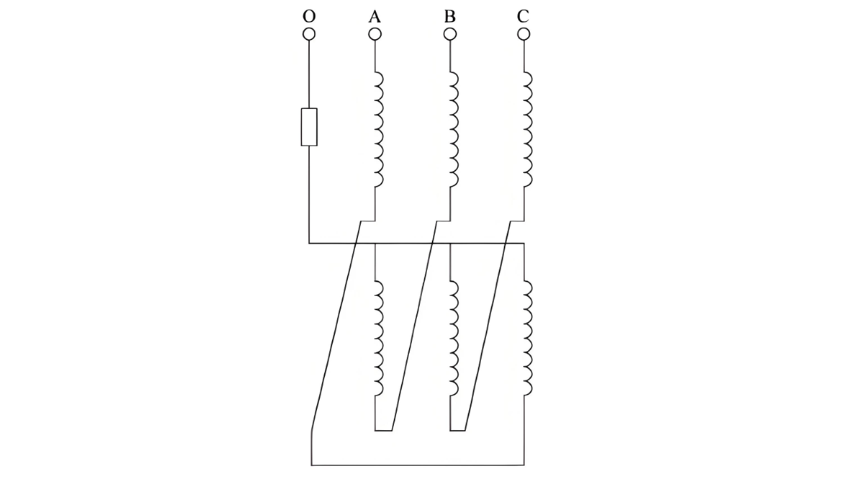
כאשר מתרחשת תקלה קצרה-مدارית באדמה, זרם סדרה אפס זורם דרך נקודת האפס. החיבור הזיגזג של טראנספורמר הצמדה מסוג Z גורם לזרמי סדרה אפס עליונים ותחתונים להתנגד אחד לשני, מצמצמים את השדה המגנטי וממזערים את העומס הסדרה אפס כדי למנוע מתח-קשת גבוה מדי. עבור זרמי סדרה חיובית/שלילית, התכונות האלקטרומגנטיות הטיפוסיות שלו יוצרות עמידות גבוהה, מגבילות את זרימתם.
במצב תפעול נורמלי, טראנספורמר הצמדה פועל כמעט ללא עומס (אין עומס שניוני). במהלך תקלה באדמה, זרמי תקלה של סדרה חיובית, שלילית ואפס עוברות דרכו. בשל "עמידות גבוהה לסדרה חיובית/שלילית, עמידות נמוכה לסדרה אפס", המכשיר הגנתי מדד בעיקר את זרם הסדרה אפס של הרשת.
2. קונפיגורציה וניתוח של הגנה נוכחת לטראנספורמר הצמדה
הגנה נוכחת לטראנספורמר הצמדה בדרך כלל משתמשת בהגנה בין-פאזה ובהגנה זרם סדרה אפס. הנה הפרטים:
2.1 הגדרת הגנה בין-פאזה
2.1.1 עקרונות הגדרה
ההגנה כוללת מפעילה מיידית והגנה עודף-זרם:
2.1.2 Tripping Modes
Based on the earthing transformer’s connection to the power supply transformer:
2.2 Setting of Zero - Sequence Current Protection for Earthing Transformers
2.2.1 Setting Principles
Since the zero - sequence current protection of the earthing transformer does not serve as the main protection, there are three time limits, which are shown as follows:

In the formula: t01, t02, t03 are the 1st, 2nd, and 3rd time limits of the zero - sequence current protection of the earthing transformer respectively; t0I' is the time setting value of Section I of the zero - sequence current of the outgoing line; t0II' is the longest time setting value of Section II of the zero - sequence current protection of all equipment on the busbar except the earthing transformer; Δt is set as 0.2 - 0.5 s.
2.2.2 Tripping Modes
2.3 Analysis of Current Protection Operation for Earthing Transformers
Analysis of the earthing transformer protection configuration shows significant differences in tripping modes between phase - to - phase and zero - sequence current protections: zero - sequence protection blocks auto - standby input during operation, while phase - to - phase protection does not.
If the zero - sequence current measured by the protection device reaches the operation value and a ground fault occurs (with the earthing transformer as the only zero - sequence current path in a small - resistance grounding system), the device detects the fault but cannot locate it. If the fault is on the outgoing line, after the protection trips the earthing transformer, the auto - standby input switches to the standby busbar. If the standby busbar recloses onto the faulty line, the earthing transformer on it still detects zero - sequence current, triggering another trip. Since the auto - standby input hasn’t finished charging, the outage range may expand. Thus, zero - sequence protection must block auto - standby input.
When phase - to - phase protection acts (but zero - sequence protection doesn’t), the device judges a phase - to - phase short - circuit in the earthing transformer itself. It trips the earthing transformer, parallel - trips the power supply transformer’s same - side circuit breaker, and the auto - standby input switches to the standby busbar. As the fault is on the tripped earthing transformer, the standby busbar reconnects to the normal line, restoring power.
In summary, phase - to - phase and zero - sequence current protections of earthing transformers differ greatly in fault cause and location judgment, requiring distinct settings and configurations. However, during a ground short - circuit, phase - to - phase protection may misoperate due to measured zero - sequence components. Given their different auto - standby input logics, misoperation may expand the fault range or even cause a full - substation blackout.
3 Case Analysis
3.1 Fault Process
The primary wiring diagram of a 110 kV substation is shown in Figure 2. Before the fault, the low-voltage side 018 circuit breaker of Transformer 1 was closed, the low-voltage side 032 circuit breaker of Transformer 2 was closed, and the 034 circuit breaker was in the test position.
At 06:14 on July 30, 2023, the over-current I section protection of the No. 2 earthing transformer activated, tripping the No. 2 earthing transformer 022 circuit breaker. Meanwhile, it interlocked to cut off the low-voltage side 032 circuit breaker of Transformer 2, causing the 10 kV Section II and III busbars to lose power. The automatic standby power supply (auto-standby) device operated to close the 10 kV Section I/II bus tie 020 circuit breaker.
At 06:36, the over-current I section protection of the No. 1 earthing transformer activated, tripping the No. 1 earthing transformer 015 circuit breaker and interlocking to cut off the low-voltage side 018 circuit breaker of Transformer 1, leading to power loss in all 10 kV Section I, II, and III busbars. The auto-standby device then closed the low-voltage side 032 circuit breaker of Transformer 2 and the No. 2 earthing transformer 022 circuit breaker. However, the fault persisted, triggering the over-current I section protection of the No. 2 earthing transformer again. The 022 circuit breaker tripped and interlocked to cut off the 032 circuit breaker, eventually causing a complete power outage in the substation's 10 kV system.

3.2 On-site Equipment Inspection Results
Primary equipment inspection findings:
Rainwater leakage from the steel support above the 10 kV Section III bus PT chamber infiltrated the switchgear, degrading insulation and causing a C-phase discharge that evolved into a metallic ground fault. In the low-resistance grounding system, the No. 2 earthing transformer detected zero-sequence currents of ~4.3 A/phase (exceeding the 2.5 A overcurrent I-section setting), triggering tripping. The overcurrent protection does not block the 10 kV auto-standby, leading to repeated operations. The final trip left the auto-standby uncharged, causing a complete 10 kV outage.
Key contributing factor: The "phase current zero-sequence cancellation" control word was disabled (set to "0"), preventing software filtering of zero-sequence components in phase currents. With a 13 A zero-sequence current, the overcurrent protection misoperated. Properly enabled, this control would have prevented the fault. Instead, the zero-sequence overcurrent protection I-section (set at 1.4 A) operated: 1st time-limit tripped the bus tie and blocked auto-standby; 2nd time-limit tripped the earthing and main transformer breakers, isolating Sections II/III while Section I remained powered.
Root cause: Disabled zero-sequence cancellation control word allowed phase current misinterpretation.
4 Conclusion
This paper outlines earthing transformer protection settings, analyzes misoperation risks under high zero-sequence currents, and presents a case study. To prevent recurrence:
Key takeaway: Proactive configuration of protection software is critical for preventing misoperations during ground faults.


