
1 מחקר על טכנולוגיית הנחת כבלים ותשתית קבל של תחנת כוח פוטו-וולטאית
1.1 איסוף נתונים
לפני בניית מודל BIM להנחת כבלים, יש להכיר לעומק את הפרמטרים המפורטים של מפרטים של הציוד שמעורר, החומרים המשמשים בבנייה והמצב באתר, במטרה לשפר את הדיוק של בניית המודל. כדי להבטיח שהמודל BIM ישקף בצורה מדויקת את מצב האתר הבנוי, העיקר הוא באיסוף וכניסה מדויקים של הפרמטרים הטכניים הספציפיים של הציוד העיקרי. אלה כוללים את הממדים המדויקים של תעלות הכבלים, המפרטים המפורטים של תיבות הפצה, הממדים החיצוניים של הכבלים ואת הפרמטרים הספציפיים של סלילי החשמל. הקשר בין הפרמטרים הללו למודל הכבל צריך לעקוב אחרי הכללים הבאים:

בנוסחה, P היא קבוצת הפרמטרים המפתח; I היא דיוק מודל ההנחת כבלים; f מעתיק את P ל-I; ו-g היא פונקציית התאמה. איסוף פרמטרים מדויק משפיע ישירות על בניית המודל מאוחר יותר והיישומיות שלו. במהלך איסוף הנתונים, פרמטרי המכשירים קשורים הדדית. שינויים בנתונים של מכשיר בודד עשויים להפעיל רצפים של תגובות, מה שמחייב התאמה בתזמון של הפרמטרים הקשורים. לכן, בשלב איסוף הנתונים, יש להתאים באופן גמיש את האסטרטגיות בהתאם לתנאי האתר כדי להבטיח אחידות ודיוק של הנתונים.
1.2 בניית מודל הכבל
בבנייה, מוליכים מתכתיים מתפחים לכבלים לאחר חיפוי. כדי לחבר את הכבלים למתקנים, מותקנים מתחברים בקצה הכבלים. מודל גיאומטרי של כבל הוא מעטפת שנוצרת מסריקה של חתך הצולב לאורך הקו המרכזי. ניתן לפשט את חתך הצולב למעגל (רדיוס r), ולהשתמש ב-R(s) = (d1(s), d2(s), d3(s)) כדי להגדיר מסגרת קואורדינטות מקומית בקו המרכזי S. הגאומטריה של הכבל מובאת במדויק באמצעות משוואה פרמטרית המתארת בניית פני המעטפת.
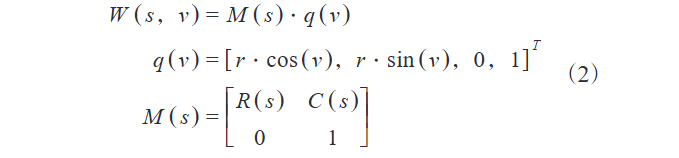
בנוסחה, W מייצגת מטריצת גבול מקומי; C(s) מייצגת נקודת מיקום קואורדינטות גלובליות; M(s) מייצגת מטריצת טרנספורמציה סיבוב. המודל הגיאומטרי של הכבל שנבנה על בסיס הנוסחה הזו מוצג בתרשים 1.
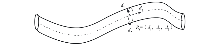
בתרשים 1, הקו המקווקו S מסמן בבירור את הציר המרכזי של הכבל. נלקח נקודת תכונה על S כנקודת צומת q, שם נבנית מערכת קואורדינטות מקומית R כדי לתאר את תכונות הכיוון של חתך הצולב. ספציפית, d1 (וקטור יחידה בכיוון הנורמלי הראשי) מגדיר את הכיוון הנורמלי הראשי של חתך הצולב; d2 (וקטור יחידה בכיוון הבינורמלי, אנכי ל-d1 משפר את תיאור הכיוון; d3 (וקטור יחידה בכיוון המשיק לאורך S) מראה את מגמת ההרחבה של הכבל ב-q. חתך הצולב ב-q מניח מעגלי עם רדיוס r0, יוצר מודל גיאומטרי מלא עם וקטורי כיוון עבור ניתוח דוגמאות כבלים עתידי.
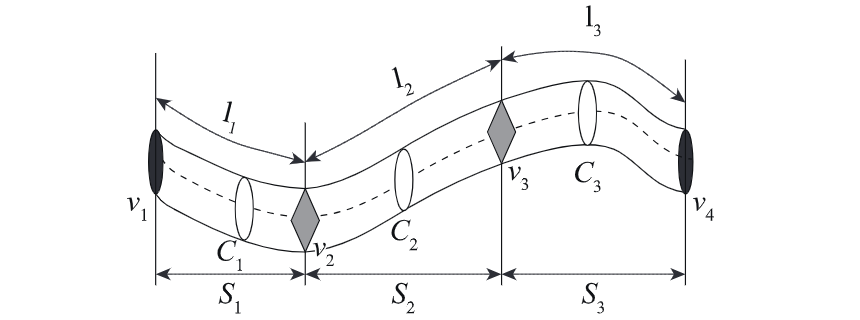
כפי שמוצג בתרשים 2, דוגמת הכבל מוגדרת על ידי ארבעה קודקודים v1-v4, המחלקים אותו לשלושה קטעים l1: v1-v2; l2: v2-v3; l3: v3-v4, כאשר v1 ו-v4 הם נקודות קצה. לכל קטע, תכונות הכיוון והצורה של חתך הצולב שלו נקבעות על ידי מיקומו/ארכו על S והמודל הגיאומטרי. לכן, הקטעים l1-l3 מתאימים לחתכים C1-C3, יחד יוצרים את הייצוג הגיאומטרי של הכבל.
1.3 הנחת כבלים
שילוב פרטים מתרשימים 1 ו-2 מאפשרתprehension of cable geometric modeling and segmentation features. The model precisely depicts core geometric elements (central axis, cross-sectional shape, directional attributes) and enables in-depth cable analysis via refined segmentation, providing a theoretical basis for efficient laying.
In pre - laying preparation, derive total lengths of cables of various specs based on the model. Organize data into standardized tables by cable type, supplying accurate info and guidelines for construction. For laying method, this project adopts direct burial to ensure professionalism and efficiency.
When laying in cable trenches, place a uniform sand/fine soil cushion to keep the cable’s bending radius within limits. Use electric winches for traction. When laying multi - core cables, strictly follow curvature radius restrictions:

In the formula, rmin represents the safe bending limit of the cable; cr represents the minimum safe turning radius of the cable. After completing the cable laying work, it is necessary to formally submit an application for hidden project acceptance to the department responsible for project quality inspection. Once the acceptance procedure is successfully passed, evenly lay fine soil on both the upper and lower sides of the cable as a protective layer, and then cover the cable with a cable cover. In addition, when planning the cable route, priority should be given to having the route closely adhere to the surface of wiring - allowable obstacles:

In the formula, qi is a specific node on the cable path centerline; OS is the obstacle surface node; Rr is the cable radius; Inter dis is the shortest distance between points.Before backfilling, review to confirm all hidden projects meet standards. Then compact the backfill to ensure its density and stability, complying with specs.
After compaction, bury direction marker stakes at key positions (cable intersections, connections, turns). Wrap cables with hemp for protection. When direct - buried cables pass through buildings, check outdoor - indoor pipe height differences; apply waterproofing if outdoor pipes are higher to ensure laying safety.
1.4 Cable Wiring
As a key link in photovoltaic power station construction, cable wiring must follow strict specs/procedures to ensure stable, reliable, and safe electrical connections.
First, prepare complete/qualified tools (wire strippers, crimping pliers, insulating sleeves, terminals, insulating tape) and materials. Ensure cables meet design specs, pass quality checks (no damage, intact insulation).
Before wiring, precisely strip cables: use wire strippers to remove outer sheaths/inner insulation per terminal requirements, expose conductors (remove burrs/oxides). Select suitable terminals based on conductor cross-sections and wiring needs. The formula is as follows:

In the formula, T is the terminal type; A is the cable conductor cross-sectional area; R denotes wiring parameters; S is the mapping function. Use crimping pliers to firmly crimp conductors and terminals, ensuring no loosening or poor contact. During wiring, strictly follow design drawings and specifications to accurately connect crimped terminals with equipment terminals, ensuring tightness.
For multi-core cables, match colors/numbers to avoid misconnections. After wiring, wrap connections with insulating sleeves/tape to enhance insulation and prevent intrusion of moisture or dust. In summary, cable wiring is critical to photovoltaic power station construction, requiring strict adherence to specifications to ensure quality and safety, laying a solid foundation for stable operation.
2 Experimental Analysis
To verify the effectiveness and feasibility of the proposed cable laying and wiring technology for photovoltaic power stations, it is compared with traditional methods.
2.1 Experimental Objects
The experiment is conducted under laboratory conditions using MATLAB for path planning simulation. Twenty standardized cable laying and wiring tasks are selected and divided into 4 groups (5 tasks each) to reduce random errors via statistical dispersion, enhancing result stability.
2.2 Experimental Preparation
Hardware includes computers with 500GB storage, 32GB memory, and Windows 10. These are debugged and optimized to ensure stable operation, accurately simulating real-world conditions for reliable results.
2.3 Experimental Results and Analysis
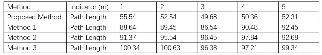
Three methods are compared with the proposed one; results are shown in Table 1.
3 Conclusion
Analyzing Table 1 data shows the proposed cable laying/wiring solution has remarkable advantages. Its path design (≈50m) is 40m, 45m, and 50m shorter than methods in 1, 2, 3. This not only proves efficient path planning but also highlights huge application potential in photovoltaic power station projects, providing valuable references for the power industry.
This paper explores cable laying/wiring for photovoltaic power stations, using BIM modeling to boost efficiency and safety. Experiments show the method outperforms traditional ones in path planning—shortening lengths and improving quality. It supports photovoltaic construction and powers sustainable industry development.
In the future, integrating intelligent construction and big data will make these technologies smarter and more efficient, driving a greener, low - carbon power industry. We expect more innovation to optimize processes, cut costs, and upgrade the global energy structure.


