
Taighde ar Teicneolaíocht Laidhreáil Cábail agus Córas Bheatha Solaí
1.1 Táirgiú sonraí
Roimh an modh BIM a thógáil do laidhreáil cábail, tá sé riachtanach go mbeadh eolas sna pointí shonracha ar sheasamh na gcuidiúcháin atá i gceist, ar na hábhair atá á n-úsáid chun tógáil, agus ar stáití na suíomh, leis an dianchruinneas a ardú sa togra. Chun cinntiú go mbeadh an modh BIM in ann léiriú cruinn ar an scéal réala a bhaineann leis an suíomh tógála, is é an príomhchuspóir ná coibhneas a bheith ann idir an modh agus an scéal réala, trí tháirgeadh agus iontráil sonraí teicniúla cruinne ar na cuidiúcháin ríochta. I measc na ndata atá á lorg, tá méadúcháin crutha cábail, seiceáil spéise foirgnimh, trastomhas cábail, agus spéise cábail. Is é an gaol idir na sonraí seo agus an modh cábail a leanas:

Sa fhoirmle, P is í an grúpa de pharáimeád ríochta; I is é an cruinneas den mhodh laidhreála cábail; f mapálann P chuig I; agus g is í an fheidhm a dhéanann an neartú. Tá tionchar mór ag cur isteach ar paramaithe ar an dtáirgeadh modh agus a úsáid. Le linn an taighde, tá comhtháthú idir na paramaithe. Athruithe ar aon duine dá lárionad féin d'fhonn a chur ar a luach, ag brath ar an dtáirgeadh modh a athrú. Mar sin, ag an am de thaighde, déan straitéis a athrú ón talamh chun a chinntiú go mbeidh an t-eolas coibhneasta agus cruinn.
1.2 Tógáil Modh Cábail
I measc na n-ábhair tógála, forbraítear cábail tar éis an chloiche a chur orthu. Chun cábail a ceangal le hionadaí, cuirtear cónnachta ar dheiridh na cábail. Is é an modh geamaíoch cábail an uillinne a fhaightear ó scannáil a chrois-dhromchla de láimh siúl ar an líne lárnach. Simplíofaí an crois-dhromchla go circe (radharc r), agus úsáideadh R(s) = (d1(s), d2(s), d3(s)) chun an ráma córdáin áitiúil a dhéanamh ar an líne lárnach S. Is é an modh geamaíoch cábail a léirítear go cruinn trí fhoirmle paraiméadartha, a léireann an tógáil uillinne.
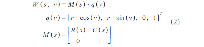
Sa fhoirmle, W léireann an matraice buanne áitiúil; C(s) léireann an puing suiteáil córdáin domhain; M(s) léireann an matraice athraithe rothlaithe. Is é an modh geamaíoch cábail a togtar bunaithe ar an fhoirmle seo mar a léirítear sa Físe 1.
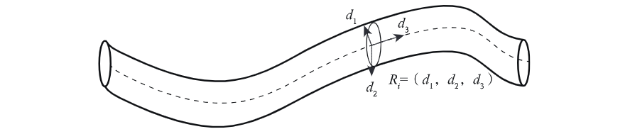
Sa Físe 1, léirítear an líne lárnach cábail S go cruinn. Tógfar puing ar S mar nód q, agus togtar an ráma córdáin áitiúil R chun an dromchla crois a dhéanamh. Go sonrach, d1 (veicteur aonair san áit príomhchothrom) léireann an treo príomhchothrom; d2 (veicteur aonair sa treo binormal, atá ingearach le d1) léireann an treo níos cruinne; d3 (veicteur aonair sa treo tagmhais de S) léireann an treo tagmhais cábail ag q. Tá an crois-dhromchla ag q mar thréadach (radharc r0), agus togtar an modh geamaíoch iomlán le veictúir treo don anailís cábail ar deireadh.
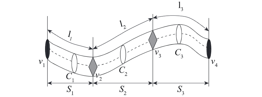
Mar a léirítear sa Físe 2, is é an sampla cábail a dhéanamh trí cheithre véithe v1–v4, agus roinnte ar trí segment l1: v1–v2; l2: v2–v3; l3: v3–v4, le v1 agus v4 mar véithe deireadh. Do gach segment, déantar a chrois-dhromchla agus a theanga a dhéanamh bunaithe ar a suíomh/ardú ar S agus an modh geamaíoch. Mar sin, segments l1–l3 correspond with cross-sections C1–C3, forming the cable's geometric representation together.
1.3 Laidhreáil Cábail
Integrating details from Figures 1 and 2 allows accurate grasping of cable geometric modeling and segmentation features. The model precisely depicts core geometric elements (central axis, cross-sectional shape, directional attributes) and enables in-depth cable analysis via refined segmentation, providing a theoretical basis for efficient laying.
In pre - laying preparation, derive total lengths of cables of various specs based on the model. Organize data into standardized tables by cable type, supplying accurate info and guidelines for construction. For laying method, this project adopts direct burial to ensure professionalism and efficiency.
When laying in cable trenches, place a uniform sand/fine soil cushion to keep the cable’s bending radius within limits. Use electric winches for traction. When laying multi - core cables, strictly follow curvature radius restrictions:

In the formula, rmin represents the safe bending limit of the cable; cr represents the minimum safe turning radius of the cable. After completing the cable laying work, it is necessary to formally submit an application for hidden project acceptance to the department responsible for project quality inspection. Once the acceptance procedure is successfully passed, evenly lay fine soil on both the upper and lower sides of the cable as a protective layer, and then cover the cable with a cable cover. In addition, when planning the cable route, priority should be given to having the route closely adhere to the surface of wiring - allowable obstacles:

In the formula, qi is a specific node on the cable path centerline; OS is the obstacle surface node; Rr is the cable radius; Inter dis is the shortest distance between points.Before backfilling, review to confirm all hidden projects meet standards. Then compact the backfill to ensure its density and stability, complying with specs.
After compaction, bury direction marker stakes at key positions (cable intersections, connections, turns). Wrap cables with hemp for protection. When direct - buried cables pass through buildings, check outdoor - indoor pipe height differences; apply waterproofing if outdoor pipes are higher to ensure laying safety.
1.4 Cable Wiring
As a key link in photovoltaic power station construction, cable wiring must follow strict specs/procedures to ensure stable, reliable, and safe electrical connections.
First, prepare complete/qualified tools (wire strippers, crimping pliers, insulating sleeves, terminals, insulating tape) and materials. Ensure cables meet design specs, pass quality checks (no damage, intact insulation).
Before wiring, precisely strip cables: use wire strippers to remove outer sheaths/inner insulation per terminal requirements, expose conductors (remove burrs/oxides). Select suitable terminals based on conductor cross-sections and wiring needs. The formula is as follows:

In the formula, T is the terminal type; A is the cable conductor cross-sectional area; R denotes wiring parameters; S is the mapping function. Use crimping pliers to firmly crimp conductors and terminals, ensuring no loosening or poor contact. During wiring, strictly follow design drawings and specifications to accurately connect crimped terminals with equipment terminals, ensuring tightness.
For multi-core cables, match colors/numbers to avoid misconnections. After wiring, wrap connections with insulating sleeves/tape to enhance insulation and prevent intrusion of moisture or dust. In summary, cable wiring is critical to photovoltaic power station construction, requiring strict adherence to specifications to ensure quality and safety, laying a solid foundation for stable operation.
2 Experimental Analysis
To verify the effectiveness and feasibility of the proposed cable laying and wiring technology for photovoltaic power stations, it is compared with traditional methods.
2.1 Experimental Objects
The experiment is conducted under laboratory conditions using MATLAB for path planning simulation. Twenty standardized cable laying and wiring tasks are selected and divided into 4 groups (5 tasks each) to reduce random errors via statistical dispersion, enhancing result stability.
2.2 Experimental Preparation
Hardware includes computers with 500GB storage, 32GB memory, and Windows 10. These are debugged and optimized to ensure stable operation, accurately simulating real-world conditions for reliable results.
2.3 Experimental Results and Analysis
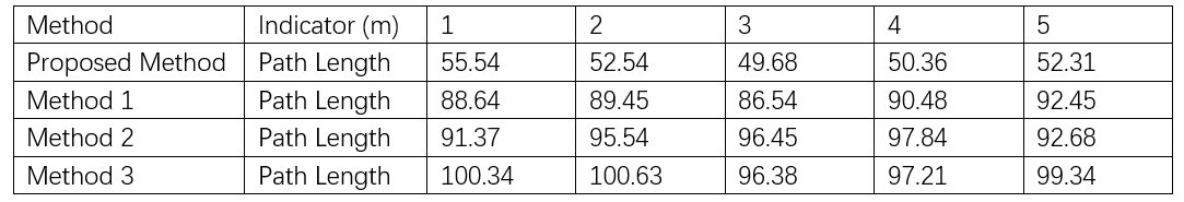
Three methods are compared with the proposed one; results are shown in Table 1.
3 Conclusion
Analyzing Table 1 data shows the proposed cable laying/wiring solution has remarkable advantages. Its path design (≈50m) is 40m, 45m, and 50m shorter than methods in 1, 2, 3. This not only proves efficient path planning but also highlights huge application potential in photovoltaic power station projects, providing valuable references for the power industry.
This paper explores cable laying/wiring for photovoltaic power stations, using BIM modeling to boost efficiency and safety. Experiments show the method outperforms traditional ones in path planning—shortening lengths and improving quality. It supports photovoltaic construction and powers sustainable industry development.
In the future, integrating intelligent construction and big data will make these technologies smarter and more efficient, driving a greener, low - carbon power industry. We expect more innovation to optimize processes, cut costs, and upgrade the global energy structure.


