Search


Why Distribution Earthing Transformers Overwhelmingly Use Zig-Zag Winding?

Distribution earthing transformers mostly use Zig‑Zag winding for zero‑sequence impedance, fault current handling, and neutral grounding.

Rockwill
Field: Manufacturing
10Year<
China
Add us on Google
 
In distribution networks (especially those with ungrounded neutral or arc-suppression-coil-grounded systems), earthing transformers overwhelmingly adopt the zig-zag winding connection. This is determined by its unique electromagnetic structure and physical characteristics. Compared with conventional Y or Δ connections, the zig-zag winding offers irreplaceable advantages when serving as an artificial neutral point. The specific reasons are as follows:
iee-business
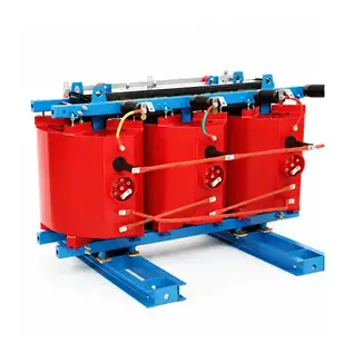
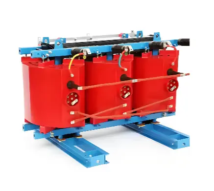
 Dry Type Zigzag (Z-Type) Grounding Transformer

1. Very Low Zero-Sequence Impedance for an Efficient Zero-Sequence Current Path

This is the core physical advantage of the zig-zag winding. Each phase winding of a zig-zag transformer is split into two halves, wound in opposite directions on two different core limbs. When a single-phase-to-ground fault occurs, the zero-sequence fluxes in the core cancel each other out due to the special reverse connection of the windings, resulting in extremely low zero-sequence impedance.

In comparison, the zero-sequence flux of conventional Y or Δ transformers can only flow through the leakage flux path, resulting in very high zero-sequence impedance. The low-impedance characteristic of the zig-zag connection ensures that fault current can flow smoothly, providing sufficient signal for protective relays.

iee-business

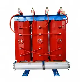
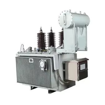
Three Phase Neutral Grounding/earthing Transformer

2. High Capacity Utilization, Breaking the "20% Limit" of Conventional Transformers

When an arc suppression coil or earthing resistor is introduced into the distribution network, the zig-zag connection demonstrates high economic efficiency. If a standard distribution transformer is used as an earthing transformer to carry an arc suppression coil, the coil capacity must not exceed 20% of the transformer capacity. In contrast, due to its self-balancing magnetic circuit design, a zig-zag earthing transformer can carry the vast majority of its own capacity as arc suppression coil load.

In practical engineering selection, the primary-side rated capacity of a zig-zag earthing transformer is typically chosen to be slightly larger than the arc suppression coil capacity.

3. No Secondary Winding Required, Minimizing No-Load Loss

If the primary neutral of a conventional transformer is grounded, a secondary winding (such as a delta winding) is required to provide a closed path for zero-sequence current; otherwise the magnetizing impedance is extremely high and zero-sequence current cannot flow. A zig-zag connection forms a zero-sequence path without requiring a secondary winding.

During normal system operation, the zig-zag earthing transformer behaves as if in an open-circuit state. Since the neutral-point voltage is near zero, only a very small magnetizing current flows through the windings, resulting in extremely low no-load loss. Zero-sequence fault current flows only during the short duration of a single-phase-to-ground fault (within seconds for zero-sequence protection operation, or up to 2 hours during arc suppression coil compensation).

4. Third Harmonic Suppression, Improving Voltage Waveform

Non-linear loads such as rectifiers and variable-frequency drives generate substantial third-harmonic currents. In conventional three-phase four-wire systems, third-harmonic currents accumulate in the neutral conductor, causing excessive neutral current and severe heating. The zig-zag connection presents low impedance to third-harmonic currents, allowing them to circulate within the windings and cancel each other, thereby effectively reducing harmonic content in the phase voltage and neutral current.

5. Magnetic Circuit Balancing, Preventing Deep Core Saturation

In an ungrounded-neutral system during a single-phase-to-ground fault, the phase-to-ground voltage of the healthy phases rises to the line voltage (i.e., an increase of sqrt(3) times). For a conventional three-limb core transformer, this voltage shift can easily cause deep core saturation, potentially damaging the transformer in severe cases. In a zig-zag connection, each phase winding is distributed across two core limbs, and the magnetomotive forces during faults achieve self-balancing through cross-coupling, effectively preventing core saturation and ensuring thermal stability during the single-phase fault period.

Summary

The use of zig-zag earthing transformers in distribution networks is essentially a means of creating an artificial low-impedance neutral point without altering the original network structure. It resolves the following engineering challenges:

  • During normal operation: The neutral-point voltage is near zero, no-load losses are minimal, and three-phase voltage balance is unaffected.
  • During a fault: Very low zero-sequence impedance provides a defined path for fault current, ensuring arc suppression coil compensation or protective relay operation.
  • Economy and safety: It overcomes the 20% capacity limitation of conventional transformers and offers strong anti-saturation capability, making it the standard and optimal choice for establishing artificial neutral points in 6 kV, 10 kV, and 35 kV distribution networks.

Edited From:Echo

Give a tip and encourage the author!

Comments

Share your question or perspective
WhatsApp
Send inquiry
+86
Click to upload file
Download
Get the IEE Business Application
Use the IEE-Business app to find equipment, obtain solutions, connect with experts, and participate in industry collaboration anytime, anywhere—fully supporting the development of your power projects and business.
Login
or continue with
New here?
Register