With local development and industrial transfer, more and more enterprises are investing and setting up factories in underdeveloped areas. However, due to the immature development of electricity load and incomplete supporting facilities such as distribution networks, the newly added load can only be connected to the existing rural power grid lines. The distribution network lines in rural areas are characterized by scattered load, small wire diameter, and excessively large power supply radius.
Connecting newly added large-capacity load to the end of the line may lead to low line voltage and excessive system line loss, thereby affecting the economic benefits of the entire system. Applying the SVR line automatic voltage regulator to the low-voltage treatment of distribution network lines can properly improve the operation quality of the distribution network system, thus ensuring power supply safety and meeting the demand for connecting newly added load.
1.Operation Principle of SVR Automatic Voltage Regulator
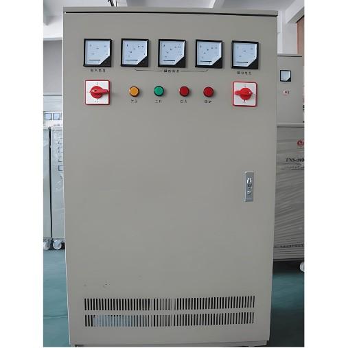
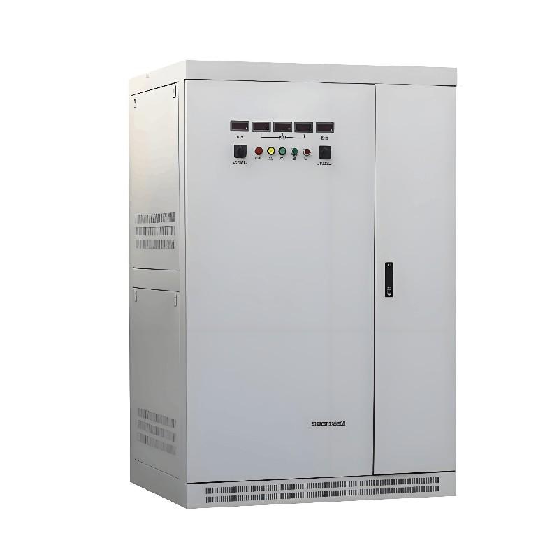
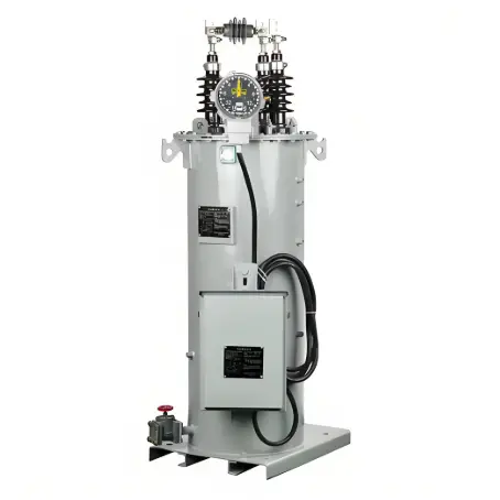
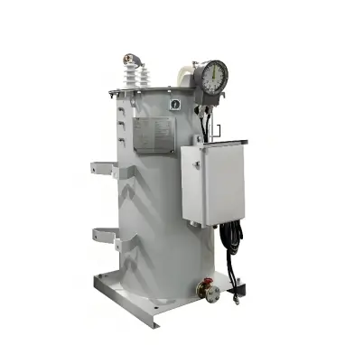
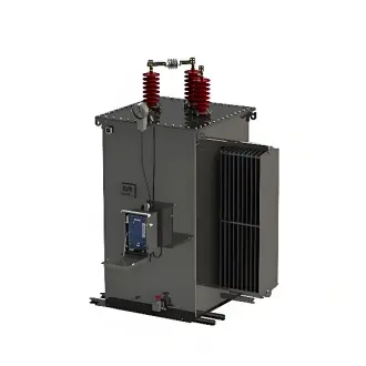
The SVR feeder automatic voltage regulation equipment is a highly automated voltage regulation device that can automatically adjust the output voltage. It is a three-phase autotransformer. At this stage, most products can automatically adjust the voltage within the range of -20% to 20%. This equipment can be installed in the feeder circuit, either in the middle position or in the low-voltage area, so as to effectively adjust and significantly control the line voltage, thereby ensuring the provision of safe and stable voltage for users. This equipment generally includes three major components, specifically: three-phase autotransformer, three-phase on-load tap changer, and intelligent controller.
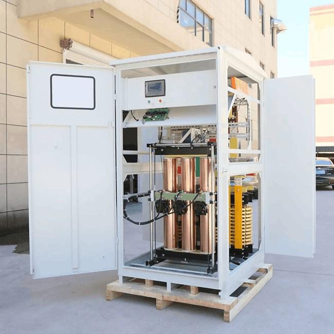
1.1 Three-Phase Autotransformer
The three-phase autotransformer equipment mainly consists of three parts: series winding, shunt winding, and control winding. Among these three windings, the series winding includes windings with several taps, which are all connected in series between the input and output ends through each contact of the on-load tap changer. The voltage ratio of the autotransformer can be adjusted by changing the tap position, so as to reasonably adjust the voltage. The three-phase shunt winding is a common winding, which itself is a magnetic field that can be used to transmit energy. The control winding can provide the necessary power energy for the operation of the controller and also provide sampling signals.
1.2 Three-Phase On-Load Tap Changer
The three-phase on-load tap changer is a special switching device that can switch contacts even under load conditions. The number of gears of the tap changer should be set in full consideration of the service life of the tap changer and the accuracy standard of user voltage regulation, which generally includes seven gears and nine gears.
1.3 Intelligent Controller
This device is mainly responsible for collecting the voltage data transmitted by the system, comparing this data with the set value, and then issuing corresponding commands to control the on-load tap changer to implement voltage regulation operations. The operation principle of this equipment is shown in Figure 1.

In Figure 1, A is the input terminal, mainly connected to the power source; a is the output terminal, mainly connected to the load. The intelligent controller can detect the voltage at the output terminal and compare it with the reference voltage. When the output terminal voltage deviates from the reference range, the controller will delay operation. If the delay duration and operation interval meet the relevant requirements, the controller will send a command to the on-load tap changer to control the rotation of the motor in the on-load tap changer, thereby driving the tap changer to switch between taps.
This adjusts the voltage ratio of the transformer to achieve the goal of on-load automatic voltage regulation. The SVR feeder automatic voltage regulation equipment adopts a three-inlet and three-outlet mode, corresponding to the three phases of the 10 kV feeder respectively, and achieves the target through the switching operation of the circuit breaker voltage regulation equipment. This equipment does not occupy a large space (generally less than 10 m²) and is more convenient and safe to locate.
2. Characteristics of SVR Feeder Automatic Voltage Regulator
Economical and efficient: The assembly cost of one voltage regulator device is about 500,000 yuan, which is relatively low and affordable. Since the equipment adopts the operation principle of an autotransformer, it can achieve a better voltage regulation effect, thus reaching the goal of economy and high efficiency.
High adjustment accuracy: At present, the most common equipment includes 7-gear and 9-gear on-load automatic voltage regulation devices, and the voltage regulation range of a single gear can reach up to -4% to 4%, making the adjustment more precise and efficient, which is convenient for voltage adjustment under various working conditions.
Highly flexible operation: Since the SVR feeder automatic voltage regulation equipment is generally connected to the feeder in a bypass series mode, it can be conveniently taken out of operation when necessary, and its voltage regulation function can also be turned off.
Low no-load loss: This equipment mainly uses an autotransformer structure, which does not produce large losses under no-load conditions. It can effectively adapt to various peak power consumption periods in rural areas, especially some off-peak periods, thus effectively preventing no-load loss problems.
Since the voltage regulator is installed in the system line in series, the feeder cannot operate in overload, so that the feeder power flow exceeds the maximum power of the equipment, which may cause equipment damage.
3. Application of SVR Line Automatic Voltage Regulator in Low-Voltage Management of 10 kV Lines
At present, SVR feeder automatic voltage regulators are equipped in 10 kV lines. Taking AB line, BC line, and CD line as examples, the application of SVR line voltage regulators is analyzed. Each line carries rural power grid loads. The overall line length is long, there are many branch lines on the main line, and the load in the entire line is not evenly distributed. The following analyzes the changes after adding feeder automatic voltage regulators in each line.
3.1 Application in AB Line
In the AB section of the 10 kV distribution network line, the main line length is 24 km, the total line length is 117.01 km, and the conductor type is LGJ-70. Its length exceeds the specified length standard, and there are many branch lines in the main line. Before reactive power compensation, the power factor of the line is about 0.9. In order to automatically adjust the line voltage and realize the reasonable distribution of electric energy, the SVR feeder automatic voltage regulation equipment is installed in the system line.
After the equipment has been in operation for one year, the voltage compliance rate on the input side of the equipment reaches 97.85%, and the voltage qualification rate on the output side reaches 100%. By adding the SVR feeder voltage regulation equipment, the voltage quality can be significantly optimized.In a certain month, observing different reference points, the input voltage and output voltage have their own change trends.
From the statistical chart, it is found that the voltage of the AB line reaches the lowest value at 9:00, which is below 90% of the rated voltage. Under the operation of the feeder voltage regulation equipment, the output voltage is 10.02 kV, and the voltage boost amplitude is about 19.86%. Under the operation of the SVR feeder voltage regulator, the voltage value can be controlled within the ideal standard range of 10~10.7 kV. After reactive power compensation, the power factor in this area is as high as 0.95, which can achieve the ideal compensation effect. However, when the reactive power capacitor is put into operation on a large scale, the voltage is relatively low, generally below 9 kV.
3.2 Application in BC Line
The length of the BC line is 20.5 km, the total line length is 174 km, and the conductor type used is relatively special (LGJ-50). There are still many branch lines in the main line. The power factor before reactive power compensation of the line is about 0.88, so the SVR feeder automatic voltage regulator is installed on this line. After 1 year of operation, the voltage compliance rate of the equipment input terminal is close to 100%, and the voltage of the output terminal is also fully qualified.
After adding the SVR feeder voltage regulation equipment, the voltage quality of the entire system has increased significantly. From the measured voltage curve, it can be seen that the voltage of this line is the lowest during 20:00~21:00, only 8.07 kV, which is below 90% of the rated voltage. Due to the effect of the feeder voltage regulator, the output voltage is 9.68 kV, and the voltage boost amplitude is 20.07%, reaching the maximum voltage regulation standard value of 20%.
3.3 Application in CD Line
The main line length of the CD line reaches 14 km, the total line length reaches 153.98 km, and the specific conductor type is LGJ-70. The power factor before reactive power compensation of the line reaches 0.9, so the SVR automatic voltage regulator (model: SVR-2000/10-7) can be installed on the line tower. After one year of operation, the voltage compliance rate of the equipment input terminal is close to 100%, and the voltage of the output terminal is also very standard, reaching 99.86%.
Adding the SVR feeder voltage regulation equipment significantly optimizes the voltage quality, but the voltage level at the input terminal is slightly insufficient to fully meet the 100% standard.From the observed voltage curve, it can be seen that there are two distinct voltage drop periods in the CD line on that day: 8:00~10:00 and 19:00~21:00. Their input voltage values are all below 9 kV. During this period, the voltage at 20:00 reaches the lowest, only 7.77 kV (only 78% of the rated voltage). The use of the SVR feeder voltage regulator can promote the voltage to be balanced and stable.
However, the output voltage at 20:00 reaches 8.82 kV, which is still in a low-voltage state. The voltage boost amplitude of the equipment is 12.51%, basically reaching the standard value of 15%.From the analysis of the actual operation status and effect of the above feeder voltage regulators, even when encountering extreme values, the voltage boost amplitude can meet the standard, so it can be concluded that the selected voltage regulators are qualified.
4. Advantages and Benefits of SVR Feeder Automatic Voltage Regulation Equipment
This voltage regulation equipment mainly achieves stable control of the output voltage by adjusting the transformation ratio of the three-phase autotransformer. In practical application, it shows the following advantages:
It can completely realize automatic, efficient, and on-load voltage regulation.
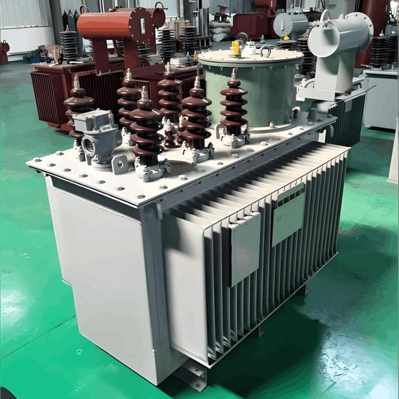
The transformer itself adopts a star-connected three-phase autotransformer, which has a large capacity and a relatively small volume, and can be erected on double poles.
The voltage regulation range is usually between -10% and 20%, which can meet the voltage requirements.According to relevant theoretical analysis and calculation, the SVR feeder automatic voltage regulator can be installed according to the specific characteristics and actual conditions of lines in different sections. After installing this voltage regulator, the voltage can be flexibly adjusted to 10.5 kV.
A large number of practical examples prove that the SVR feeder automatic voltage regulation complete set of equipment has a high degree of automation and intelligence functions, can dynamically track the fluctuation of the input voltage, thus ensuring the relatively stable performance of the constant output voltage, and effectively overcoming the problem of low voltage.After installing the SVR voltage regulation equipment in the low-voltage line, compared with building a new substation, the replacement of conductors can effectively control capital investment, thus effectively controlling the line voltage, and also responding to the relevant national departments, thus bringing better social and economic benefits.
When the line load remains constant, by increasing the line voltage, the line current is effectively controlled, thus greatly controlling the line loss, improving the power transmission efficiency, and finally achieving the goal of energy saving and loss reduction.Compared with building a new substation, the SVR voltage regulator effectively controls capital use by updating conductors, so that the voltage of the entire system line is increased, which meets the relevant national industry regulations, achieves ideal economic benefits, and also brings certain social benefits. When the line load remains stable, by increasing the line voltage, the line current can be effectively controlled, thus controlling the line loss to a certain extent, achieving the goal of energy saving and loss reduction, maintaining the economic benefits of the power supply enterprise, and effectively suppressing its economic loss, thus improving the overall economic benefit.
5.Conclusion
In areas with limited load development space, few power source layouts, large power supply radius, serious line loss, heavy load, and no planned 35 kV substation in the near future, it is suitable to install SVR feeder automatic voltage regulation equipment to control the system operation problems. This can not only efficiently control the voltage quality problem but also minimize the line loss, so as to obtain ideal economic and social benefits. The application of this equipment can also effectively control costs, improve the operation efficiency of the power system, and create ideal social benefits.