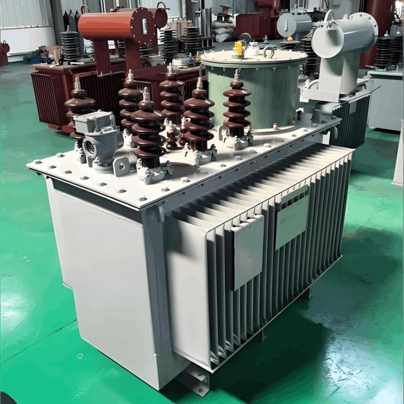
When evaluating power quality, voltage is a critical influencing factor. Voltage quality is typically assessed by measuring voltage deviation, fluctuation, waveform distortion, and three-phase symmetry—with voltage deviation being the most important indicator. To ensure high voltage quality, voltage regulation is generally required. Currently, the most widely used and effective method for voltage regulation involves adjusting the tap changer of power transformers.
This paper primarily integrates PLC and microcomputer technologies to design and analyze an intelligent power voltage regulator, ultimately achieving rapid voltage regulation while avoiding transient voltage surges during the adjustment process.
1. Working Principle and Key Features of the Intelligent Power Voltage Regulator
1.1 Main Working Principle
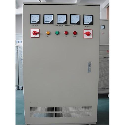
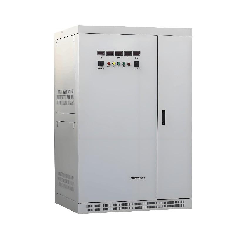
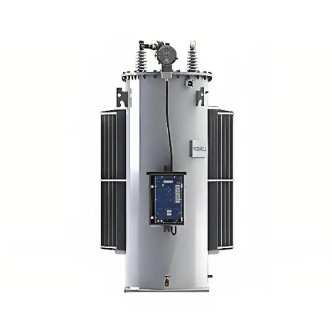
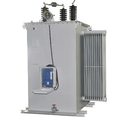
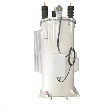
The intelligent power voltage regulator consists of a main unit and auxiliary units. The main unit comprises primary and secondary capacitors along with a regulating transformer, enabling both reactive power compensation and automatic voltage regulation.
The auxiliary units include one intelligent control unit and three execution adjustment units. The intelligent control unit generates and transmits control commands, which are received wirelessly by the execution units to enable real-time voltage regulation on the distribution line.
As the core component, the intelligent control unit determines the device’s automation level, intelligence, and regulation accuracy. It precisely monitors feeder voltage, generates appropriate commands, and sends them to the tap changer control module to maintain the feeder voltage at the target setpoint. Its main functions include:
Real-time monitoring and control of feeder voltage—promptly correcting any deviations;
Real-time monitoring and control of output load current;
Providing protective functions against undervoltage, overcurrent, and overheating conditions.
The intelligent power voltage regulator offers the following advantages:
Dual functionality: It simultaneously provides reactive power compensation and voltage regulation. During voltage adjustment, it also partially compensates for grid reactive power, improving power factor, preventing line damage, enhancing grid load capacity, and ensuring voltage quality. Additionally, it can monitor three-phase voltage and current.
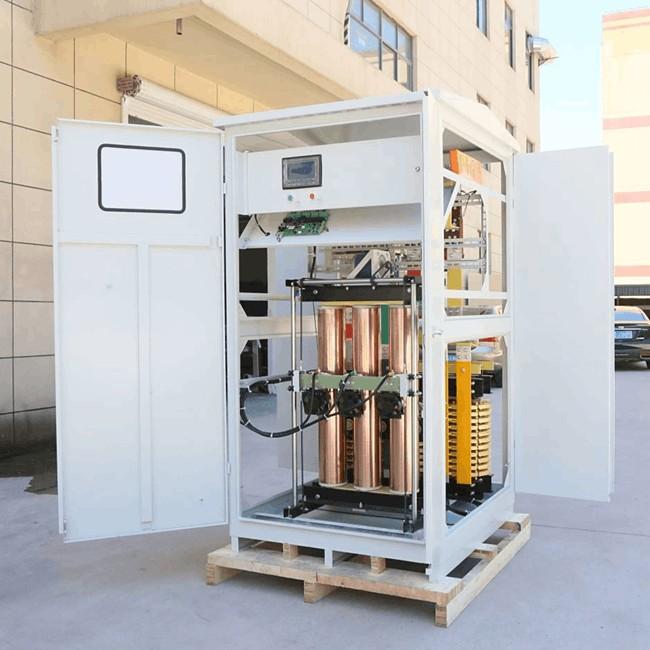
Optimized and eco-friendly structure: The design employs graded insulation to increase dielectric strength. Data transmission between the control and execution units uses voltage isolation, enabling oil-free signal transfer. All voltage and current sensors are integrated internally, eliminating the need for external potential or current transformers—enhancing reliability, stability, and ease of installation.
Intelligent voltage regulation: It automatically measures tap positions based on user-defined thresholds and self-corrects inaccurate settings to ensure stable grid operation.
Maintenance-free tap changer operation: By connecting the regulating transformer in series with reactive compensation capacitors, short-circuit currents during voltage adjustment remain low, minimizing operational impact.
Intelligent protection: Continuously monitors line load and transformer temperature; automatically exits regulation mode upon detecting anomalies and resumes operation once conditions normalize.
Real-time data logging: The control unit accurately records voltage, current, and the number of tap changes before and after each regulation event.
Efficient wireless communication: On-site data can be read directly, and regulation parameters (e.g., time intervals, voltage thresholds) can be adjusted remotely—simplifying operation.
Given its high cost-effectiveness, reliability, and safety, the intelligent power voltage regulator is well-suited for widespread deployment in rural power grids, significantly reducing voltage deviation issues.
2. Application of PLC Control Technology in the Hardware Design of the Intelligent Power Voltage Regulator
Based on the functional requirements and technical specifications of the intelligent power voltage regulator, its hardware architecture is illustrated in Figure 1.

The microcontroller basic system primarily adopts an industrial personal computer (IPC), utilizing a CPU card model named All2In2One with 256MB of memory, featuring two serial and one parallel interface. Additionally, it uses a PCI2S3-compatible graphics acceleration chip, with the graphics card size ranging from 1 to 2MB. To enhance system reliability, low-power components are employed to reduce current consumption.
During the setup of input channels, input signals are identified as secondary signals from voltage and current transformers. These signals undergo conditioning before being converted via ADC for input into the MCU. The signal conditioning circuit mainly consists of current and voltage transformers along with a three-stage operational amplifier. Current and voltage transformers effectively convert high voltages and currents into smaller ones with high precision and good linearity. The three-stage op-amp amplifies these converted and rectified signals.
For this intelligent power voltage regulator, a Panasonic series FP1 PLC is selected, offering up to 5000 steps of program capacity, simple operation commands, and comprehensive functionality. It also employs RS485 twisted pair cables, achieving a transmission rate of 100bps and enabling networking of up to 32 PLCs within a range of 1200 meters. This PLC model features excellent monitoring capabilities, capable of real-time monitoring of ladder diagrams and dynamic timing to ensure smooth voltage regulation.
Output channels adopt logical output methods. To achieve steady voltage regulation through minimal switching voltage and crossover current, zero-crossing triggering is required, alongside setting up contactless electronic switches.
After powering on and initiating the intelligent power voltage regulator, initialization and self-check procedures must be conducted. Upon successful self-check, it determines whether the device is in operating mode or configuration mode. In configuration mode, parameters can be set using a keyboard by entering the setup menu, selecting specific settings, and adjusting values with up/down keys. In operating mode, sampling and digital filtering occur, followed by choosing appropriate voltage regulation methods:
Automatic Regulation: Executes corresponding programs to judge if the voltage is within the specified range. If so, no adjustment is needed; otherwise, adjustments are made to bring the voltage back within limits.
Manual Regulation: Manual operations via panel buttons adjust voltage levels. After completing voltage adjustments, display programs show transformer secondary voltage and current values, as well as daily regulator actions, ensuring continuous operation.
To meet user requirements for voltage deviation, effective application of control algorithms is essential. This involves calculating values independent of sampled time points from discrete data sets through mathematical operations, comparing them with design specifications, and performing logic operations for tap changer adjustments. The calculation formulas for measuring current, voltage, and active power are as follows:
(Note: The specific formulas for current, voltage, and active power measurement were not provided in your text, but typically involve standard electrical engineering calculations such as Ohm's law, power factor calculations, etc.)
These descriptions provide a detailed explanation of how the intelligent power voltage regulator operates, its hardware configuration, and the software processes involved in maintaining optimal voltage regulation.

In the formulas, i(k) and u(k) represent the k-th current sampling value and voltage sampling value, respectively. Based on these, other quantities such as Q and cosφ can be derived and calculated.
Through testing the intelligent power voltage regulator, this paper finds that the device can effectively adjust the voltage in a short time, avoiding problems such as surges and short circuits, ensuring the stability of voltage regulation, and achieving a relatively ideal voltage regulation effect. It can be seen that the application of PLC control technology in the intelligent power voltage regulator can effectively realize the automatic detection and regulation of voltage, accelerate the voltage regulation speed, and the actual operation is relatively simple. Moreover, no surge occurs during voltage adjustment, and the upper computer can monitor various working states of the device in real time, which plays a great role in the transformation and management of substations and distribution stations.